Y070.302/EN Page 45
Operation instructions
SIPOS SEVEN: PROFITRON, HiMod
7
Commissioning
7 Commissioning
7�3 Valve parameters
Operation sequence
1. Turn Drive Controller in th “Valve” menu until
the settings for CLOSE
and OPEN
are shown under "Tripping torque“ parameter
in the display.
2. If the tripping torque for end position
CLOSED is to be changed, for example, set
selection marker to the value to be changed
andconrm.
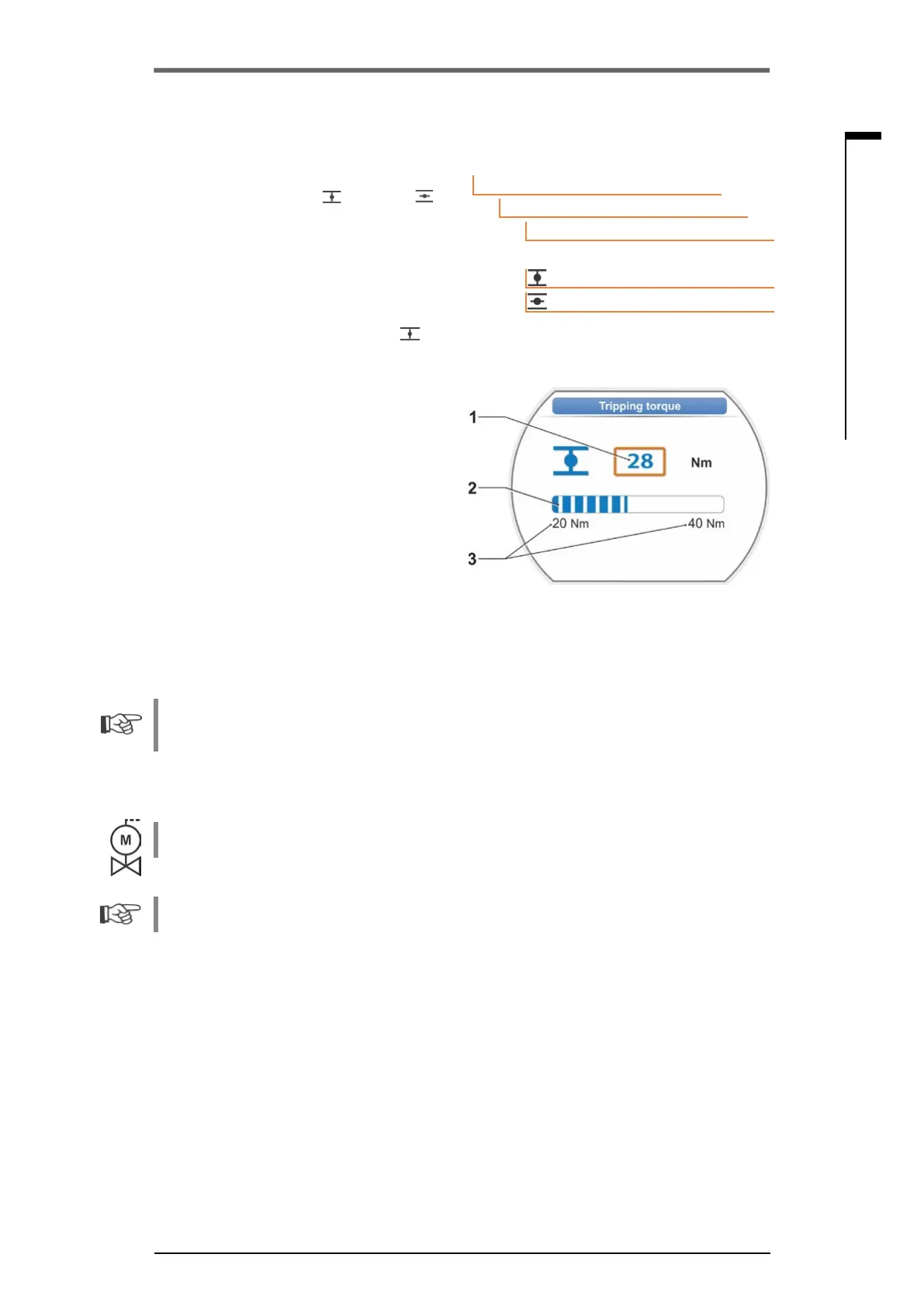
Display changes to "Tripping torque
"
settingmenu(refertog.)andthecurrent
valueisashing(g.,item1).
3. Turn Drive Controller until desired value is
displayed.
The progress bar (item 2) shows the current
position within the setting range (3).
4. Conrmselectedvalue.
Display returns to "Valve" menu.
5. Proceed accordingly to set tripping torque in
end position OPEN.
Main menu
Parameter
Valve
28 Nm
20 Nm
Tripping torque
Fig� 2: Tripping torque setting menu
Fig� 1: Navigation to "Tripping torque” pa-
rameter
7�4 Adjust end positions for version with signaling gear
PROFITRON actuators are either available with signaling gear or as "non-intrusive“ version with
the non-intrusive position encoder. End position adjustment for HiMod and PROFITRON with the
non-intrusive position encoder is described in chapter 7.5.
7�4�1 General information
If actuators are delivered mounted to a valve, this step has usually been done in the valve manu-
facturer’s factory. The setting has to be checked during commissioning.
For 2SG7 and 2SQ7 part-turn actuators, the signaling gear ratio does not have to be set. These
actuators are not equipped with an adjustable signaling gear. Continue with chapter 7.4.3
Position recording functional principle
By setting the signaling gear ratio and the end positions, it is ensured that length as well as start
and end of the valve travel (end positions OPEN and CLOSED) are correctly signaled to the elec-
tronics unit.