Operation instructions
SIPOS SEVEN: PROFITRON, HiMod
Page 44 Y070.302/EN
7 Commissioning
7.3 Valve parameters
7
Commissioning
Tripping torque/tripping force
The setting determines the torque or force to be achieved in relation to the load, to cause the motor
to trip. This applies to torque/force-dependent tripping in the end position as well as to a block. For
this reason, tripping torque or force also have to be set for travel-dependent cut-off mode.
Thetrippingtorque/trippingforceofanactuatorisbasedonthesizing,denedbytheapplication.
The tripping torque of the actuator is listed on the name plate.
A programmed addtional gear is considered during programming (refer to chapter „7.2 Additional
gear“ on page 36): The values for tripping torque/force are converted using the factor output/input
torque or input torque/output force and displayed. Only those values are provided for programming
in the display which are revelant to the combination of the actuator with the connected gearbox.
Setting values are displayed accordingly:
– Rotary gearbox: Tripping torque [Nm];
– Linear thrust unit: Tripping force [kN];
– Part-turn gearbox: Tripping torque [Nm].
The setting range for actuators of classes A and B ranges from 30 – 100 % and for modulating
actuators of classes C and D from 50 – 100 % in 10 % steps of the maximum torque each (for
some additional gears, other limit values apply) Default setting is the lowest possible value (typically
30 % of the maximum value for classes A and B, and 50 % of the maximum value for classes C and
D).
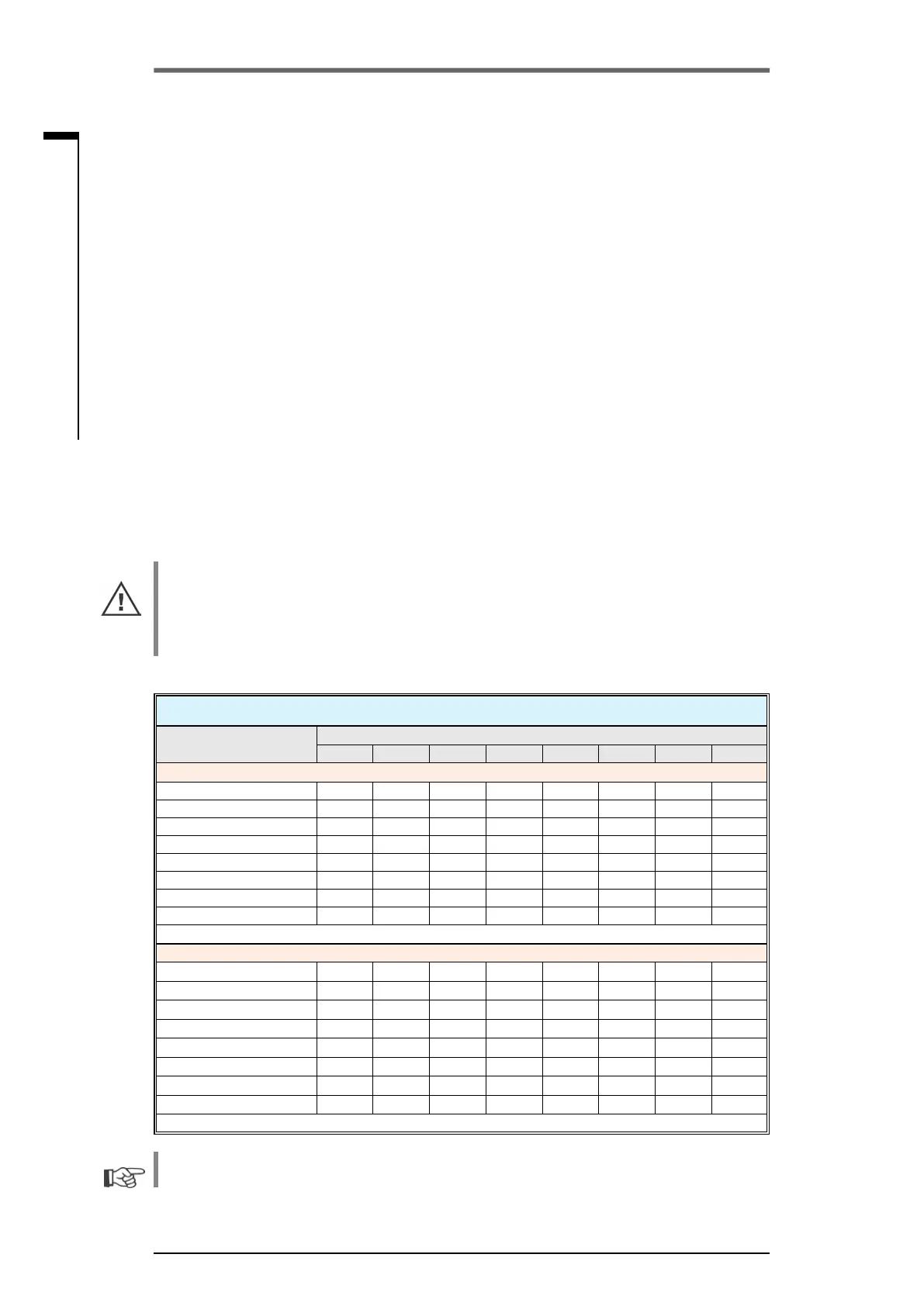
The following table shows the possible parameter values without additional gear.
■
For 2SG7 part-turn actuator, the tripping torque cannot be changed.
■
For 2SQ7, the tripping torque can be set via the torque switching, refer to supplement to opera-
tion instructions Y070.449.
■
If a cut-off mode or torque setting is selected that is not appropriate for the valve, the valve may
be damaged!
Tripping torques (without additional gear)
Tripping range [Nm]
Possible values for setting in Nm of Md
max
30 % 40 % 50 % 60 % 70 % 80 % 90 % 100 %
Classes A and B (type of duty in compliance with EN 15714-2)
9 – 30 9 12 15 18 21 24 27 30
18 – 60 18 24 30 36 42 48 54 60
37 – 125 37 50 62 75 87 100 112 125
75 – 250 75 100 125 150 175 200 225 250
150 – 500 150 200 250 300 350 400 450 500
300 – 1000 300 400 500 600 700 800 900 1,000
600 – 2000 600 800 1,000 1200 1400 1600 1800 2000
1200 – 4000 1200 1600 2000 2400 2800 3200 3600 4000
▲30 % are set as standard
Classes C and D (type of duty in compliance with EN 15714-2)
10 – 20 10 12 14 16 18 20
20 – 40 20 24 28 32 36 40
40 – 80 40 48 56 64 72 80
87 – 175 87 105 122 140 157 175
175 – 350 175 210 245 280 315 350
350 – 700 350 420 490 560 630 700
700 – 1400 700 840 980 1120 1260 1400
1400 – 2800 1400 1680 1960 2240 2520 2800
▲50 % are set as standard
For reasons of simplicity, the designation “torque” shall also apply to force in the following de-
scription. For example, instead of torque or force dependent, only torque dependent will be used.