Operation instructions
SIPOS SEVEN: PROFITRON, HiMod
Page 18 Y070.302/EN
4 Instructions on operator control and operation
4
Instructions on operator control and operation
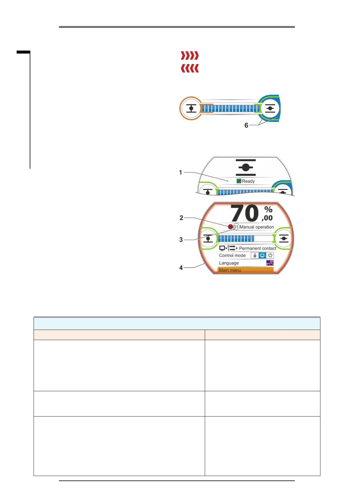
The actuator state is indicated in the display,
refertog.,item1.
If a fault has occurred, the display shows a
warningsymbol(g.,item2)andahintwith
regard to potential causes. If the actuator is not
ready for operation, the display is framed in red
(item 4).
By selecting the fault signal, additional informa-
tion, e.g. possible remedies, are indicated.
Thegureinfrontofthemessage(g.,item3)
refers to the type of fault and allows unambigu-
ousidenticationbytheservicestaff.
Therstdigitoftheguresignies:
0 = operational state;
1, 8 = self-resetting fault;
2 = acknowledgeable fault;
3 = fault due to external causes;
4, 5, 6 = fault within the device.
For a detailed description of possible fault sig-
nals, refer to the table below.
Status messages in the display including explanation
Signal Explanation Possible remedy
01 Manual mode
■
Hand wheel/crank handle is pressed.
■
Cable to the hand wheel is defective
■
Pull hand wheel/crank handle and/or
■
Check feed cables and contact points of
electronics/gear!
Should this message occur sporadically, vibra-
tion could be the cause.
In this case, use brackets. Refer to „4.1 Crank
handle, hand wheel“ on page 15.
02 Emergency mode
An EMERGENCY signal is present.
The parameterized EMERGENCY position is approached.
03 Blocked in move
A block has been detected within actuator travel.
The actually required torque exceeds the set tripping torque
or
"Separatemounting"parameterissetto">10mwithlter",
althoughthereisnoLClteravailable.
Operate actuator into opposite direction. Should
the message occur rather frequently,
■
Check valve and torque setting, increase trip-
ping torque if necessary or
use the ”Move again if blocked in move“ func-
tion!
■
Check MOV for sluggishness.
■
Check "Separate mounting“ parameter.
Fig�: Status indication
4 Should a block occur during operation, the
respective status message is indicated and
the remaining travel is represented as red
hatched area,refertog.2
5 If an EMERGENCY position or a setpoint
is being approached, the target position is
indicated by a symbol (vertical line on the
position bar).
6 If the actuator is in one of the end positions,
the respective symbol is shaded in blue.
= Block in OPEN direction
= Block in CLOSE direction
Fig� 2: Indication of operation direction dur-
ing block
Fig� 3: Indication Actuator in end position
OPEN
4�3 Actuator status indication