Operation instructions
SIPOS SEVEN: PROFITRON, HiMod
Page 48 Y070.302/EN
7 Commissioning
7.4. End positions – Signaling gear
7
Commissioning
The setting procedure can be aborted by selecting "Back" . The formerly valid end position
adjustment is maintained unless the central wheel was turned.
1. Select LOCAL control
.
2. Select ‘End positions' menu item in the 'Main
menu'.
Display changes to ‘End positions’ menu.
3. Conrm"Newsetting"menuitem.
Display changes to ‘Only end positions’
(g.2,item1)or‘Complete’settingquery,
including all parameters required for correct
end position adjustment (item 2).
These parameters include:
– CLOSE direction (clockwise or counter-
clockwise)
– Speed (in OPEN and CLOSE directions)
– Cut-off mode (torque-dependent or travel-
dependent in end positions CLOSED and
OPEN)
– Tripping torque (in end position CLOSED
and end position OPEN)
These parameters have already been de-
scribed in chapter 7.3.
4. Select "Only end position" menu item and
conrm.(For2SG7and2SQ7,continuewith
step 11).
Display changes to "Remove signaling gear
cover" animation.
5. Loosen4screws(g.3,item1)fromthe
signaling gear cover and remove cover.
6. Select ‘Continue’ in the display.
Display changes to ‘Adjust signaling gear
ratio to valve’.
7. Accept incremental value either from
– Additional gear menu, refer to „Signaling
gear setting“ on page 39‚
– or from table „Signaling gear setting with-
out additional gear“ on page 47.
andadjustslidewheel(g.3,item.2)sothat
the gear rim faces the desired incremental
value on the scale.
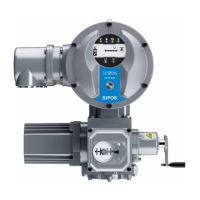
Fig� 1: End position readjustment
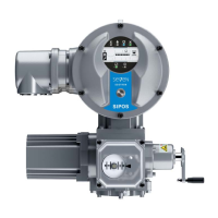
Fig� 2: End position setting with or without
parameters
Fig� 3: Adjust signaling gear ratio
7�4�3 Procedure for initial end position adjustment
The end positions are directly set at the actuator.
The valve must not be jammed. Use the crank handle/hand wheel for release, if necessary. For
crank handle/hand wheel operation, refer to chapter „4.1 Crank handle, hand wheel“ on page 15.