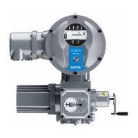
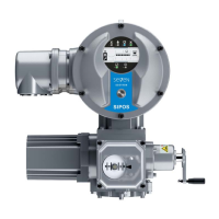
Operation instructions
SIPOS SEVEN: PROFITRON, HiMod
Page 14 Y070.302/EN
3 Assembly and connection
3
Assembly and connection
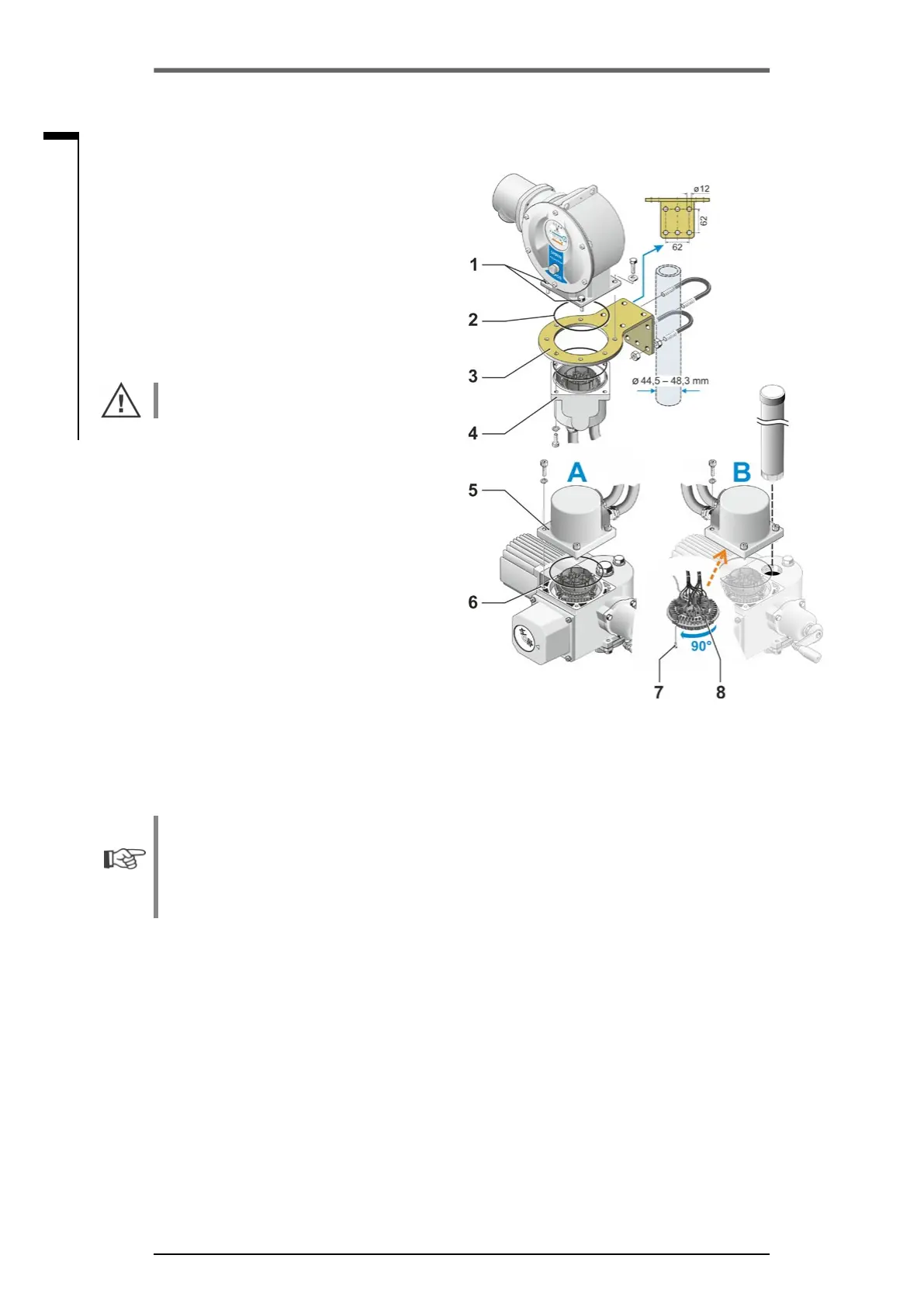
3�3 Separate mounting
If the ambient conditions such as extreme
vibration, high temperature and/or if access is
difcult,theelectronicsunitistobemounted
separately from the gear unit.
The assembly kit for mounting the gear unit
and electronics unit separately can be ordered
directly with the actuator or separately as an ac-
cessory (2SX7300-...). The assembly kit is pre-
assembled. If the assembly kit is ordered directly
with the actuator, it is included separately with
the actuator.
Before starting the work, disconnect actuator
from the mains!
Procedure
1. Installmountingbracket(g.,item3)atthe
mounting location of the electronics unit.
2. Remove electronics housing (1) from the gear
unit (6) and mount it on the mounting bracket
(3) with the O-ring (2).
3. Standard assembly, refer to A
Fit "Separate mounting“ assembly kit: Plug
cover with contact pins (4) on lower side of
wall bracket (3) and plug cover with contact
sockets (5) on the gear unit (6).
4. Assembly with stem protection tube, refer
to B
Turn connection hood by 90° or 180° to en-
sure that cables are not impaired by the stem
protection tube:
Remove screws (7) from round plug, turn
roundplugby90°to180°andxscrews
again. Continue as described in section 3.
Fig�: Separate mounting
A = Standard,
B = with stem protection tube
■
Duringinstallation,itisimportanttoensurethattheO-ringsarettedcorrectlyinordertoguar-
antee the degree of protection.
■
Generally, it has to be ensured that movable parts, e.g those of the swing lever, are not im-
paired by the cables.
■
In exceptional cases, the motor might become very hot. Therefore the cables should not touch
the motor.
Specication of the connecting cable between the electronics unit and the gear
unit
The connecting cables are available in different versions:
■
Standard lengths: 3 m, 5 m, 10 m;
■
withadditionalequipment(lter)upto150m.
Forseparatemountingexceeding10mincludinglter,thevalue">10mwithLClter“hastobe
set for the "Separate mounting" parameter. Refer to “Special parameters” section „8.6.2 Separate
mounting“ on page 84.
The actuator can also be equipped with a remote control unit that allows local operation in
distances up to 100 m. The remote control unit has the function of a second local control unit.
Refer to „9.4 Remote control unit“ on page 96.