Operation instructions
SIPOS SEVEN: PROFITRON, HiMod
Page 46 Y070.302/EN
7 Commissioning
7.4. End positions – Signaling gear
7
Commissioning
Explanation
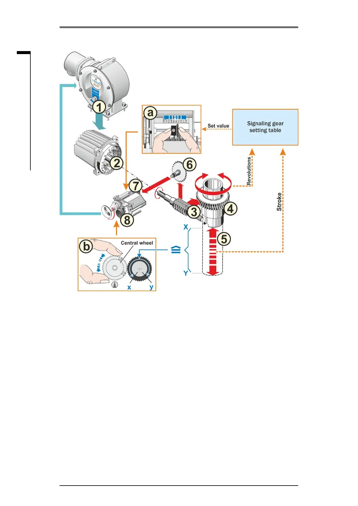
From the position of the potentiometer (8), the electronics unit recognizes the position of the output
drive shaft (4) and therefore the position of the connected valve.
Two settings are required:
1. The signaling gear (refer to a in illustration) reduces the rotations of the output shaft (4) required
for the complete travel [(5) X to Y]toarotarymovementof≤300°(x to y) of the potentiometer
(8).
2. One of the mechanical end positions of the valve (X or Y) corresponds to one limit of the electric
setting range of the potentiometer (x or y) (refer to b in illustration),
For a detailed description, refer to the following chapters „7.4.2 Signaling gear ratio“ and „7.4.3
Procedure for initial end position adjustment“.
Fig�: Schematic representation of the signaling gear ratio and end position settings