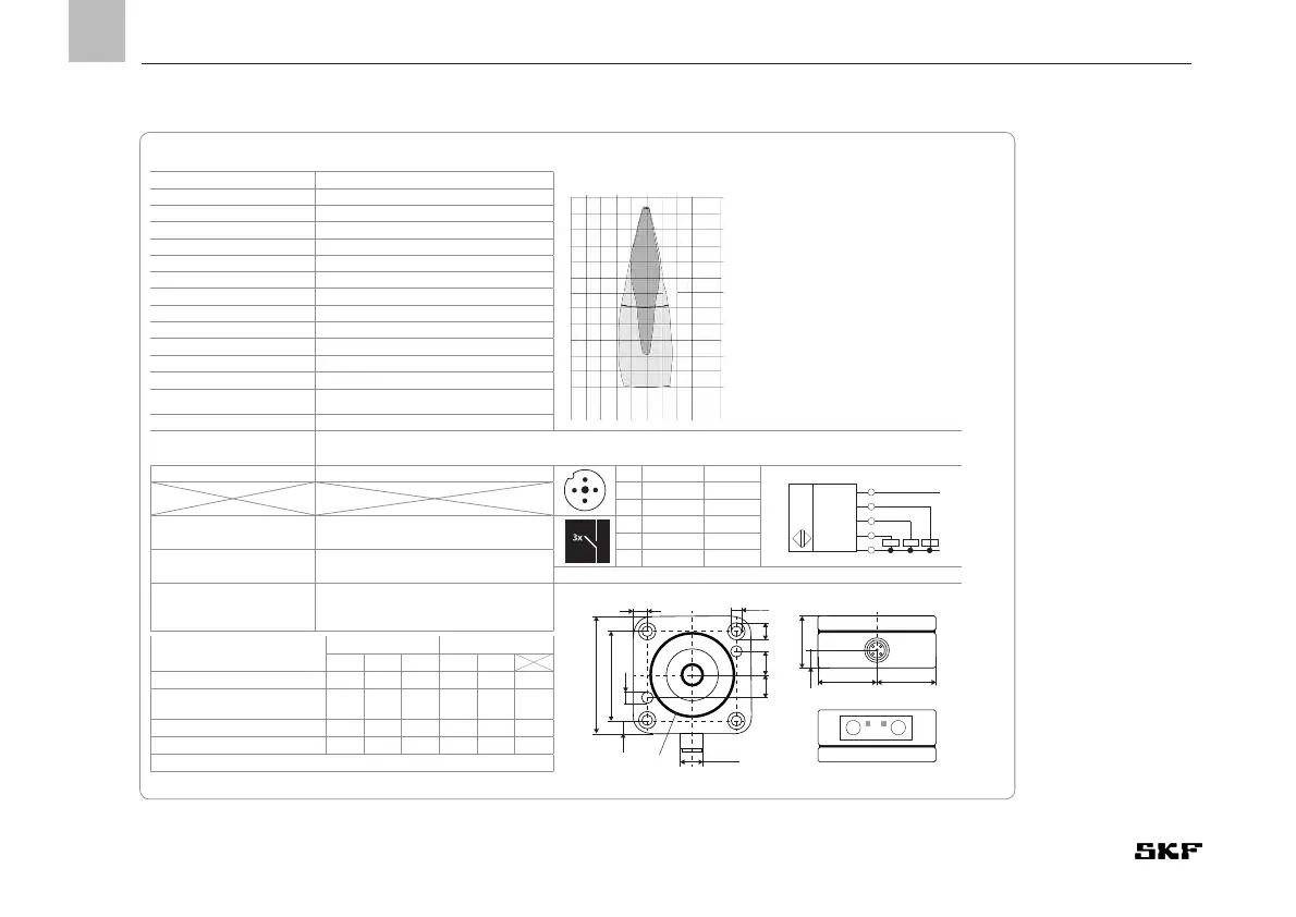
0 10 201020
0
10
20
30
40
50
60
35
cm
cm
Detection zone in centimetres
The dark grey areas indicate the
zone in which the standard reflec-
tor (pipe) is reliably detected. This
is the typical operating range of
the sensors, The light grey areas
indicate the zone in which a big
reflector – like, e.g. a plate – is still
detected – provided it is optimally
positioned to the sensor. Outside
the light grey area an evaluation is
not possible any more.
Blind zone 0 - 65 mm
Scanning range limit 600 mm
Ultrasonic frequency approx. 400 kHz
Switching frequency 3.7 Hz
Resolution 0.18 mm
Accuracy ±1 %
Repeatability ±0.15 %
Operating voltage U
B
9 - 30 V DC (polarized)
Residual ripple ±10 %
No-load supply current ≤60mA
Type of connection M12 x 1 plug; 5-pole
Response delay 272 ms
Readiness delay < 300 ms
Type of protection following EN 60529
IP 65
Range of operating temperatures -40 °C to + 70 °C
Switch points
High-level indication D1 = 65 mm; low-level indication D2 corresponding to the reservoir size; pre-low-level indica-
tion D3 programmable on customer request, pre-set to 10 mm above low-level (optional use possible)
Compliance with standards EN 60947-5-2
1
2 4
3
5
1 + U
B
brown
U
1
2
4
5
3
3 - U
B
blue
4 D2 black
Display elements
LED green / LED red
Switching output not set/ set
3x
2 D1 white
5 D3/Com grey
Housing material
PBT, polyester, ultrasonic transducer:
PUR, epoxy resin with glass content
Dimensions
Switching output
3x pnp; UB-2V; lmax = 3x 200 mA; NO
contact, short-circuit resistant
47
62,2
7,6
7,6
M12x1
13,3 13,3
5,2
5,2
8,5
31,1 31,1
26,7
11
T1 T2
D1 D2
Display of the switching states
Switch points Indication by LED
D1 D2 D3 D1 D2
High-level indication A A B red red C
Between high- and pre-low-
level indication
B A B green red C
Pre-low-level indication B A A green red D
Low level indication B B B green green C
A = switched, B = not switched, C = permanent, D = flashing