SECTION 5, Page 27SJKB-40-D, SJKB-40-D/F
JUN. 1999
CAUTION
BRAKE ADJUSTMENT PROCEDURE
Hydraulic
1. Block wheels to prevent machine from rolling.
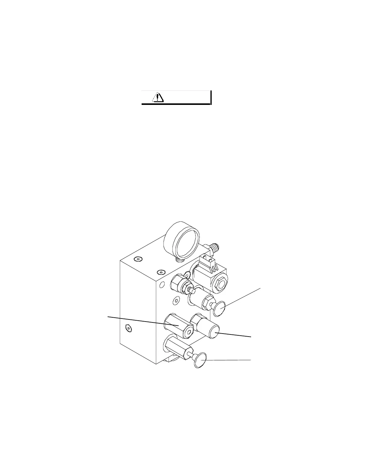
2. Locate brake system pressure reducer. Refer to Figure 5-19 for location
3. Remove cap from pressure reducer and turn adjuster GENTLY clockwise until it bottoms out.
4. Pull out brake release override (red knob). Refer to Figure 5-19 for location.
5. Locate brake system relief valve. Refer to Figure 5-19. for location.
6. Pump brake release hand pump. See Figure 5-19. Adjust releif valve to 700 PSI on gauge.
7. Push brake release override valve in.
8. Start engine from platform controls and extend boom slightly to achive low speed drive.
9. Drive machine forward or reverse and observe pressure gauge. should read 600 - 650 PSI.
10. Stop machine and adjust pressure reducing valve 1/4 turn at a time until 600 - 650 pressure reading is achived.
Turn clockwise to increase or counterclockwise to decrease.
PRESSURE
REDUCING
VALVE
RELIEF
VALVE
Valve damage will occur if tightened too much!
Ma40-524
Figure 5-19. Brake System Manifold.
BRAKE
RELEASE
OVERRIDE
VALVE
BRAKE
RELEASE
HAND PUMP