EasyManua.ls Logo

Smartgen HMC6

Smartgen HMC6
87 pages
To Next Page IconTo Next Page
To Previous Page IconTo Previous Page
Loading...
HMC6 Power Management Controller User Manual Page 27 of 87
9. HARDWARE STRUCTURE
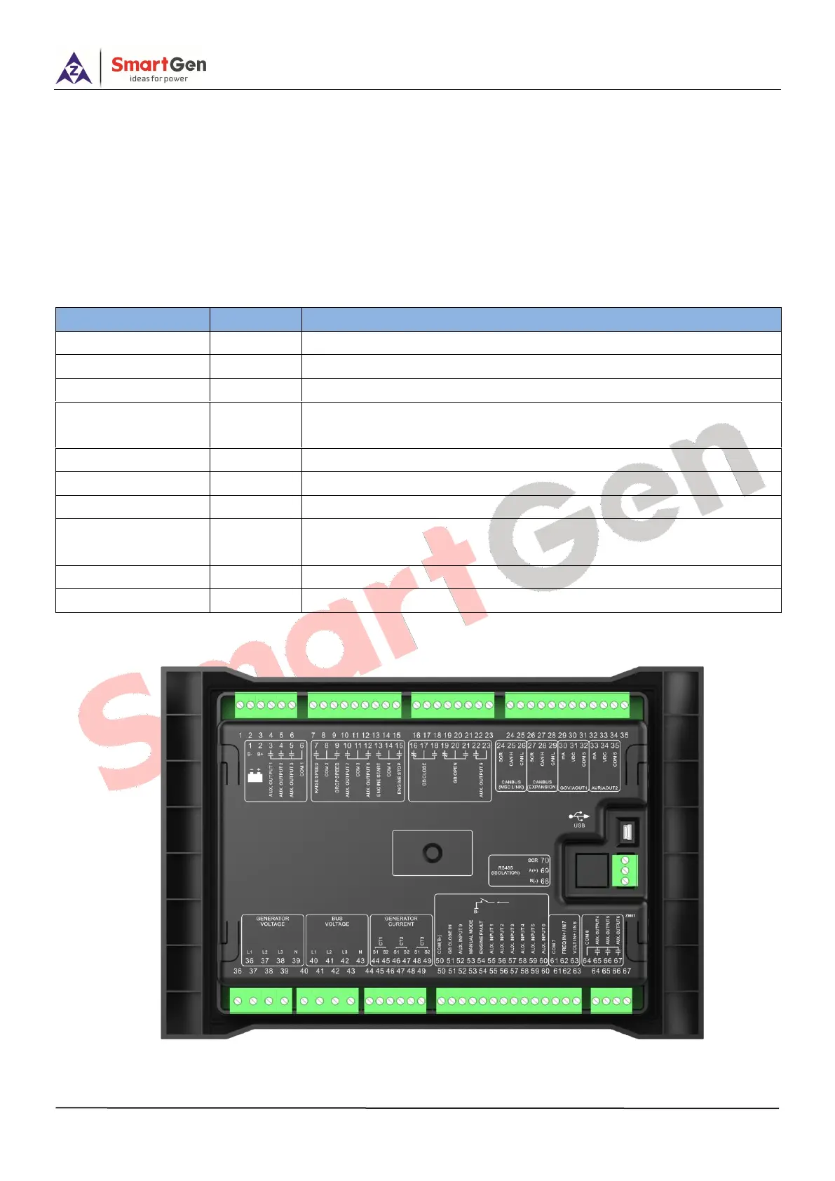
9.1 STRUCTURE DESCRIPTION
HMC6 terminals are standard configuration. Uses only can expand 16-channels discrete input module,
16-channels discrete output module or 16-channels LED lamp module via CANBUS (Expand) port to realize
expansion.
Table 10 HMC6 Terminals
Slot
Terminal
Remarks
Slot #1
1-6
Power supply; reply output port
Slot #2
7-15
Relay output port
Slot #3
16-23
Relay output port
Slot #4
24-35
CANBUS port; GOV analog speed regulator port; AVR analog voltage
adjustment port.
Slot #5
36-39
Generator voltage input
Slot #6
40-43
Busbar voltage input
Slot #7
44-49
Generator current input
Slot #8
50-63
Digital input port, external frequency modulation, voltage adjustment
port
Slot #9
64-67
Relay output port
Slot #10
68-70
RS485 COM port
9.2 TERMINAL DESCRIPTION
Fig.3 HMC6 Terminal Drawing

Table of Contents

Related product manuals