- 53 -
No.EX##-OMY0004
10.3. Wiring
Caution
●To prevent damage, all power for the SI Unit and modules must be turned off (i.e. de-energized) before
the modules are installed or removed.
●For a protection rating of IP65 to be ensured, sockets that are not used must be closed with M12 covering
caps.
●For a protection rating of IP65 to be ensured, all covering caps must be screwed down correctly after
wiring and setting have been performed.
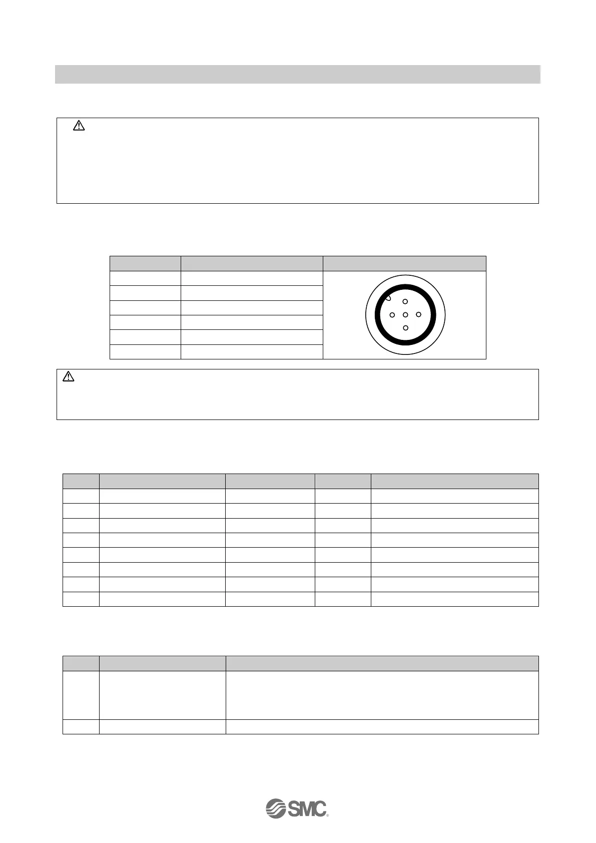
Pin allocation of the M12, 5-way socket connector as shown in the following table:
Table 10-2 Safe input connectors
View of connector (Module side)
WARNING: Loss of safety function
Parasitic voltages can result in the loss of the safety function.
●Connect the sensor ground directly to Pin 3 0V (US1) of the safety module. An external ground may not
be used.
10.4. Safe digital I/O - Safe digital inputs
Table 10-3 Byte 0 Safe digital inputs
Input status of safe input 0
Input status of safe input 1
Input status of safe input 2
Input status of safe input 3
Input status of safe input 4
Input status of safe input 5
Input status of safe input 6
Input status of safe input 7
Note: In case of “1oo2 evaluation”, input status of safe input 4-7 (Byte 0, bits 4 – 7) is fixed to 0: OFF
Table 10-4 Byte 1 Status bits (only applies to Safety Mode (Module Passivation/xxx))
Status bit for
parameterization using
Safety Mode (Module
Passivation/xxx)
0: NOK (Fault state). SI unit has not received a process image for the
PROFIsafe parameters or the received process image is invalid
1: OK. Process image for PROFIsafe parameters received and valid.
Byte 2-5: Reserved for PROFIsafe communication container specified by PROFIsafe.

 Loading...


