Caution
To prevent damage, all voltages to the SI Unit must be turned off (i.e. de-energized) before the modules
are installed or removed.
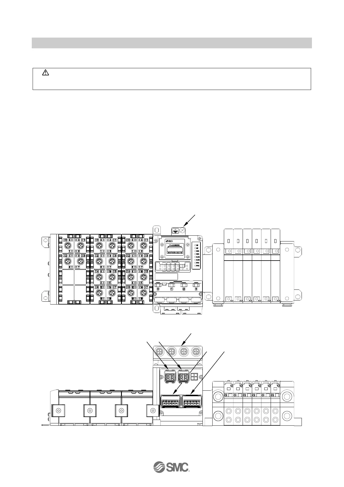
Wire the grounding cable, the PROFINET cables and the power cable.
EX245-FPS1
① M5, FE terminal screw (torque = 1.5 Nm)
② Push Pull connector (SCRJ), PROFINET connection Port1 (XF1)
③ Push Pull connector (SCRJ), PROFINET connection Port2 (XF2)
④ Push Pull connector (24 Volt), Power connection (XD1)
⑤ Push Pull connector (24 Volt), Power connection (XD2)
⑥ M12 Connector, Safe Inputs
EX245-FPS2
① M5, FE terminal screw (torque = 1.5 Nm)
② Push Pull connector (RJ45), PROFINET connection Port1 (XF1)
③ Push Pull connector (RJ45), PROFINET connection Port2 (XF2)
④ Push Pull connector (24 Volt), Power connection (XD1)
⑤ Push Pull connector (24 Volt), Power connection (XD2)
⑥ M12 Connector, Safe Inputs
Fig. 7-4 Screw and connector allocation (EX245-FPS1/2)

 Loading...


