- 77 -
No.EX##-OMY0004
12.3. Wiring
Caution
●To prevent damage, all power for the SI Unit and modules must be turned off (i.e. de-energized) before
the modules are installed or removed.
●For a protection rating of IP65 to be ensured, sockets that are not used must be closed with M12
covering caps.
●For a protection rating of IP65 to be ensured, all covering caps must be screwed down correctly after
wiring and setting have been performed.
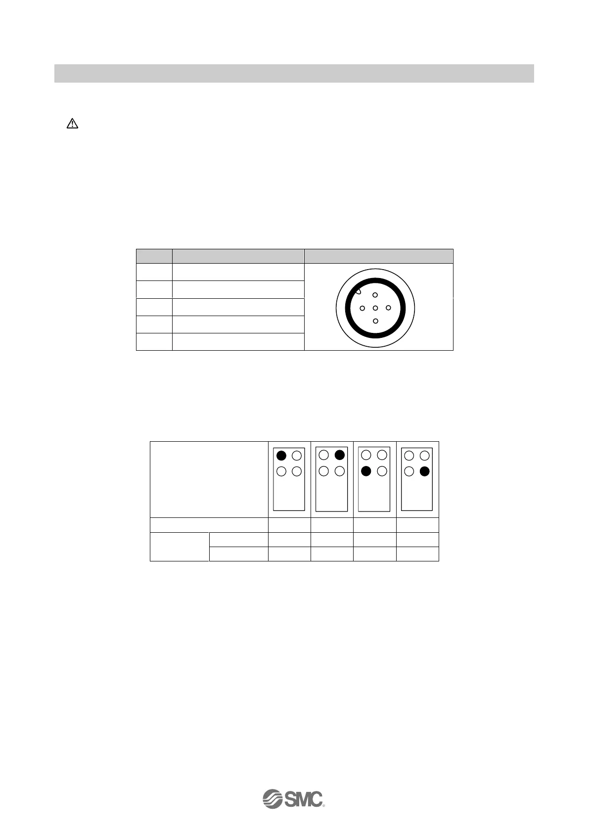
Pin allocation of the M12, 5-way socket connector as shown in the following table:
Table 12-2 Pin allocation of the connector for EX245-DY1
12.4. Process data
The EX245-DY1 occupies 1 byte of output data. The following table shows the allocation of the digital
outputs and the process image.
Table 12-3 Digital output allocation and the process data

 Loading...


