- 44 -
No.EX##-OMY0004
9. Diagnosis
9.1. Diagnostics data on I/O mapping
The EX245-FPS1/2/3 can be allocated diagnostics data as digital input data on I/O mapping, if one of the
modules, “Diagnostics type 1” or “Diagnostics type 2”, is used. Use the PROFIsafe master’s software to
select a diagnostics module type to allocate the diagnostics data on I/O mapping.
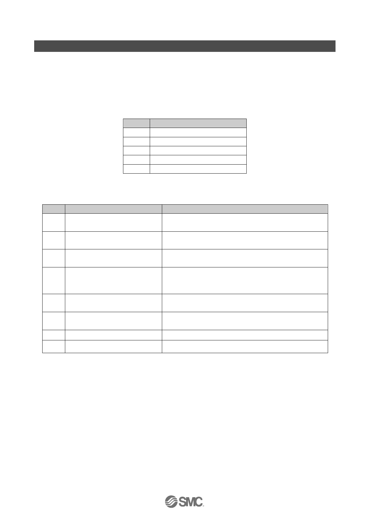
9.1.1. Diagnostics type 1
Table 9-1 Overview of Diagnostics type 1
9.1.1.1. General diagnostics 1
Table 9-2 General diagnostics 1
0: No error
1: At least one error has occurred
Valve-coil(s) short circuit
0: No valve coil(s) have a short circuit
1: At least one valve coil has a short circuit
0: No module has an error
1: At least one connected module has an error
0: Module layout has not changed
1: Module layout has changed or is different from Configuration
setting
0: US1 present (> approx. 21.6 VDC)
1: US1 has dropped (< approx. 17.0 VDC)
0: US2 present (> approx. 22.8 VDC)
1: US2 has dropped (< approx. 17.0 VDC)

 Loading...


