EasyManuals Logo
Home>SMC Networks>Control Unit>EX245-FPS1

SMC Networks EX245-FPS1 User Manual

SMC Networks EX245-FPS1
113 pages
To Next Page IconTo Next Page
To Previous Page IconTo Previous Page
Page #44 background imageLoading...
Page #44 background image
- 43 -
No.EX##-OMY0004
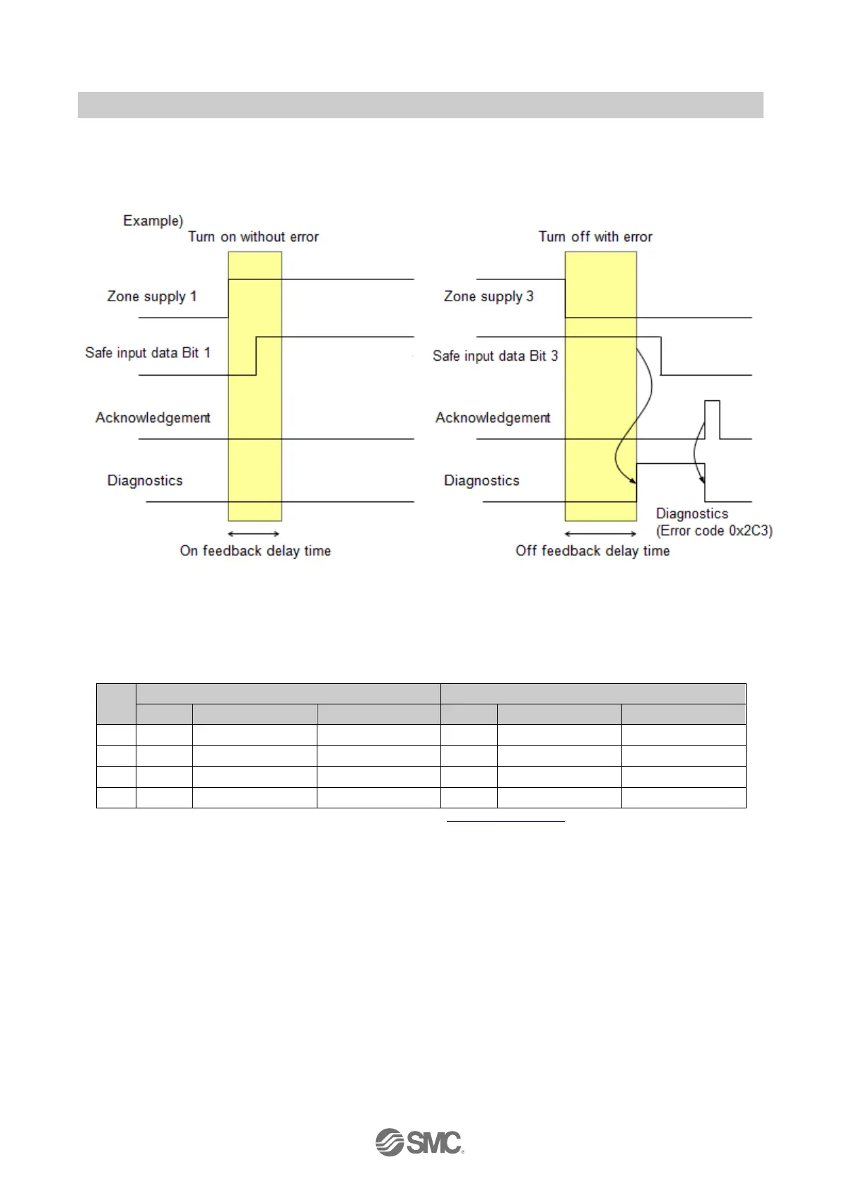
Output feedback parameter
If the parameter is enabled, the EX245 evaluates the bit status of a safe input according to the status of
the safe power supply.
Relationship between safe power supplies and safe inputs
If the parameter is enabled, the relationship in the following table between the safe power supply and
safe input is applied.
Table 8-5 Relationship between safe power supplies and safe inputs
No.
Safe power supply
Safe input
Bit
Description
Label ()
Bit
Description
Label ()
1
0
For I/O modules
M
0
Safe input 0
IN0 [0 and 4]
2
1
For valve zone1
Z1
1
Safe input 1
IN1 [1 and 5]
3
2
For valve zone2
Z2
2
Safe input 2
IN2 [2 and 6]
4
3
For valve zone3
Z3
3
Safe input 3
IN3 [3 and 7]
() Signal identities as described on product label. Refer to Section 10.9.2 LED Indicators 2

Table of Contents

Questions and Answers:

Question and Answer IconNeed help?

Do you have a question about the SMC Networks EX245-FPS1 and is the answer not in the manual?

SMC Networks EX245-FPS1 Specifications

General IconGeneral
BrandSMC Networks
ModelEX245-FPS1
CategoryControl Unit
LanguageEnglish

Related product manuals