- 22 -
No.EX##-OMY0004
5. Power Supply Concept
5.1. Power distribution
In the EX245 PROFIsafe product series, the supply for the logic input modules and hence sensors is
designated “US1” The supply for the valves and logic output modules and hence loads is designated “US2”.
To provide the safety function, the “US2” supply is switched by separate high-side switches to each of the
three valve zones (zone 1, zone 2 and zone 3) to the manifold and to any directly connected output modules
as a fourth zone. The return supply from the module zone (zone M) is switched by a low side switch and the
return supply from all the three valve zones is switched by another low side switch.
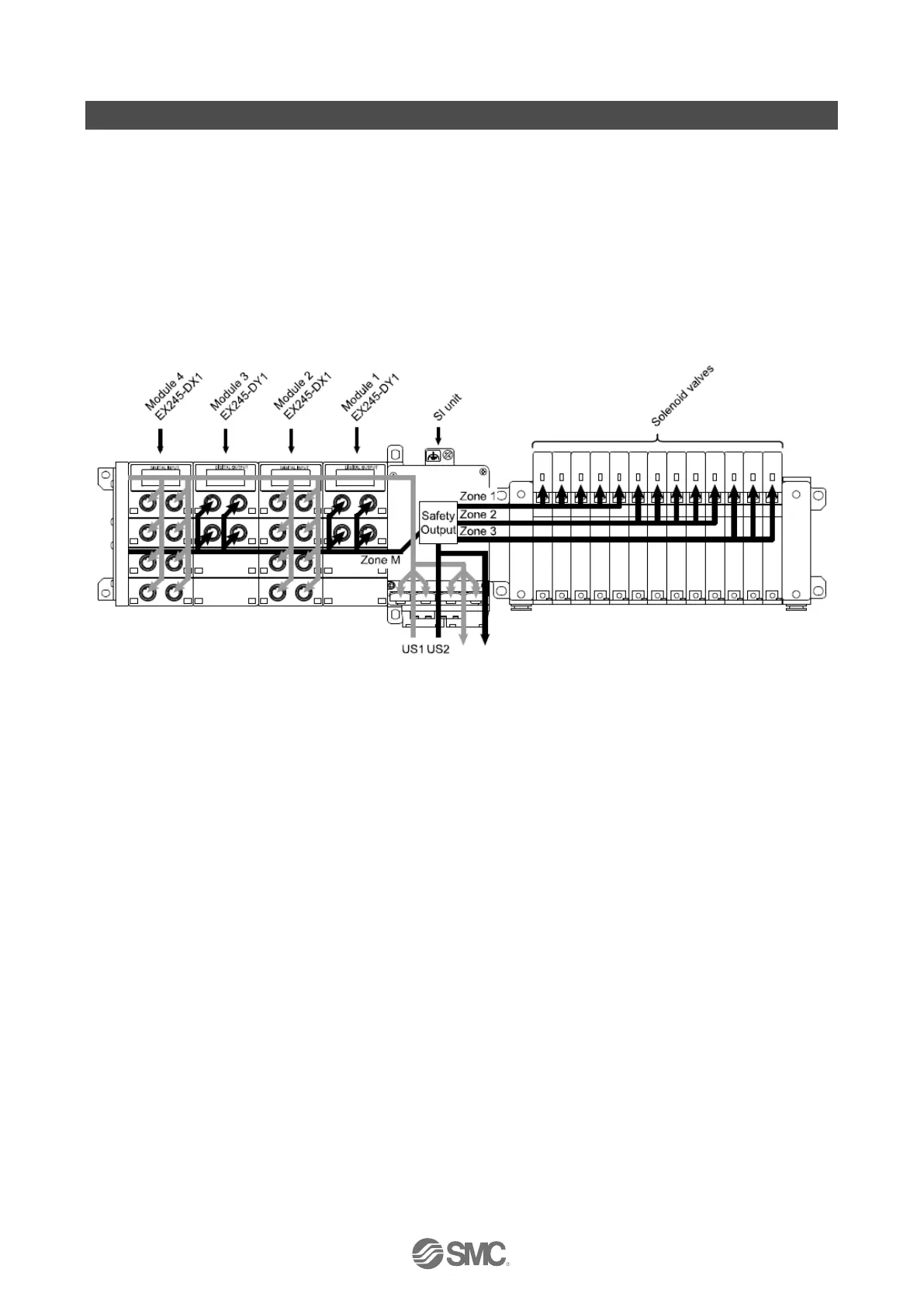
Example
Fig. 5-1 Diagram of power supply concept (example)
SI unit provides US1 and safely switched supply to the valves and module 1 and 3.
All digital input modules (Module 2 and Module 4 in this case) are operated by US1.
US1: 6 A max.
US2: 4 A max.
Galvanically isolated supplies (US1 to US2).

 Loading...


