EasyManuals Logo
Home>SMC Networks>Control Unit>EX245-FPS1

SMC Networks EX245-FPS1 User Manual

SMC Networks EX245-FPS1
113 pages
To Next Page IconTo Next Page
To Previous Page IconTo Previous Page
Page #62 background imageLoading...
Page #62 background image
- 61 -
No.EX##-OMY0004
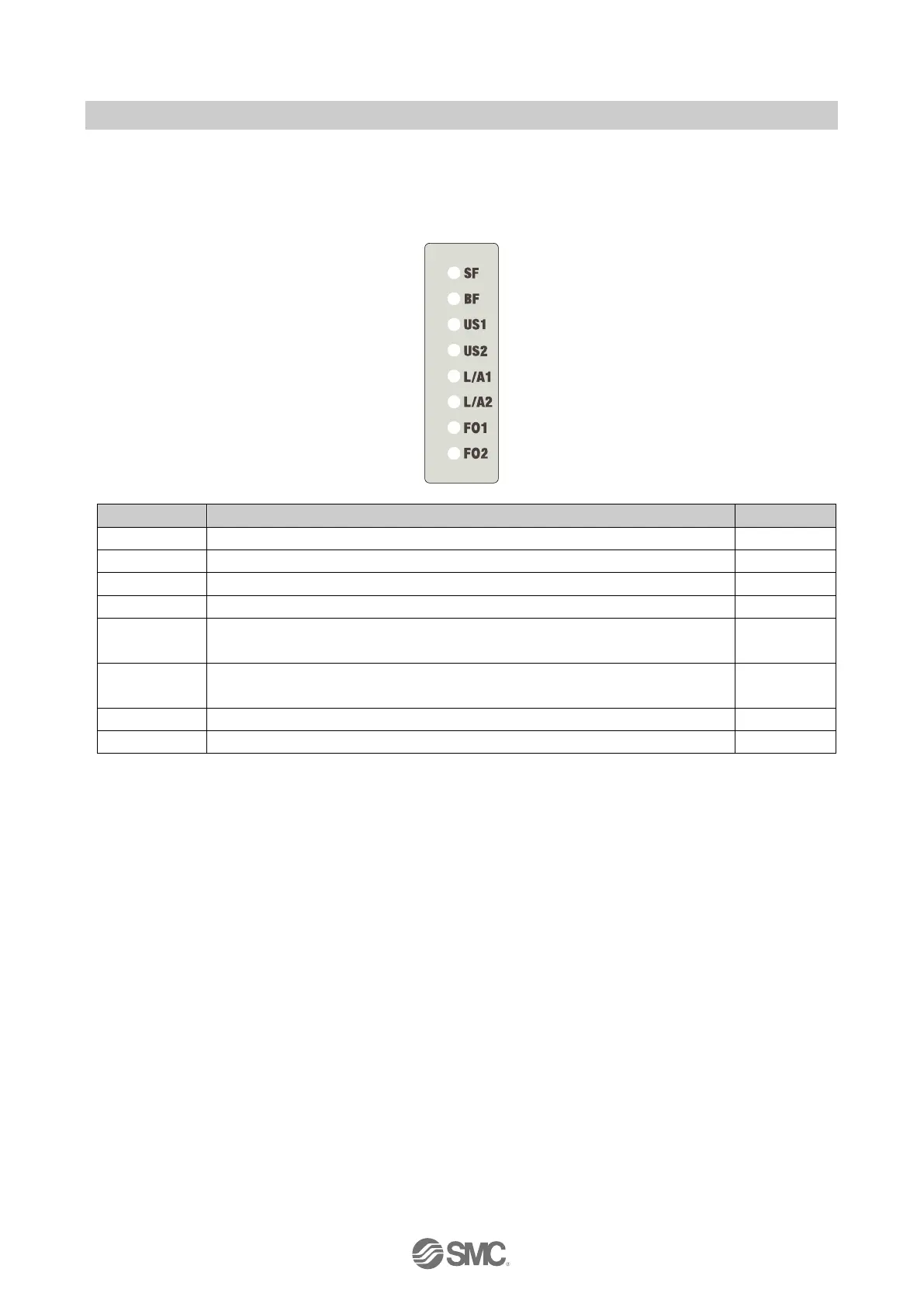
10.9. LED indicators
10.9.1. LED indicators 1
The LED indicators 1 are arranged on the SI Unit as shown in the illustration below
Designation
Description
Colour
SF
System fault
Red
BF
Bus fault
Red
US1
Supply for the logic/sensors
Green
US2
Supply for the valves/loads
Green
L/A1
A combination of Link LED and Act LED.
Connection via PROFINET on Port1 (XF1), and Data exchange on Port1 (XF1)
Green/Yellow
L/A2
A combination of Link LED and Act LED.
Connection via PROFINET on Port2 (XF2), and Data exchange on Port2 (XF2)
Green/Yellow
FO1 **
Fibre-Optic communication diagnostics for Port 1 (XF1)
Orange
FO2 **
Fibre-Optic communication diagnostics for Port 2 (XF2)
Orange
: When Link LED and Act LED are both on the combined colour may appear to be orange
**. Only EX245-FPS1 has this function
Fig. 10-4 LED indicators 1 of the EX245-FPS1/2/3

Table of Contents

Questions and Answers:

Question and Answer IconNeed help?

Do you have a question about the SMC Networks EX245-FPS1 and is the answer not in the manual?

SMC Networks EX245-FPS1 Specifications

General IconGeneral
BrandSMC Networks
ModelEX245-FPS1
CategoryControl Unit
LanguageEnglish

Related product manuals