- 62 -
No.EX##-OMY0004
10.9.1.1. SF and BF indicators
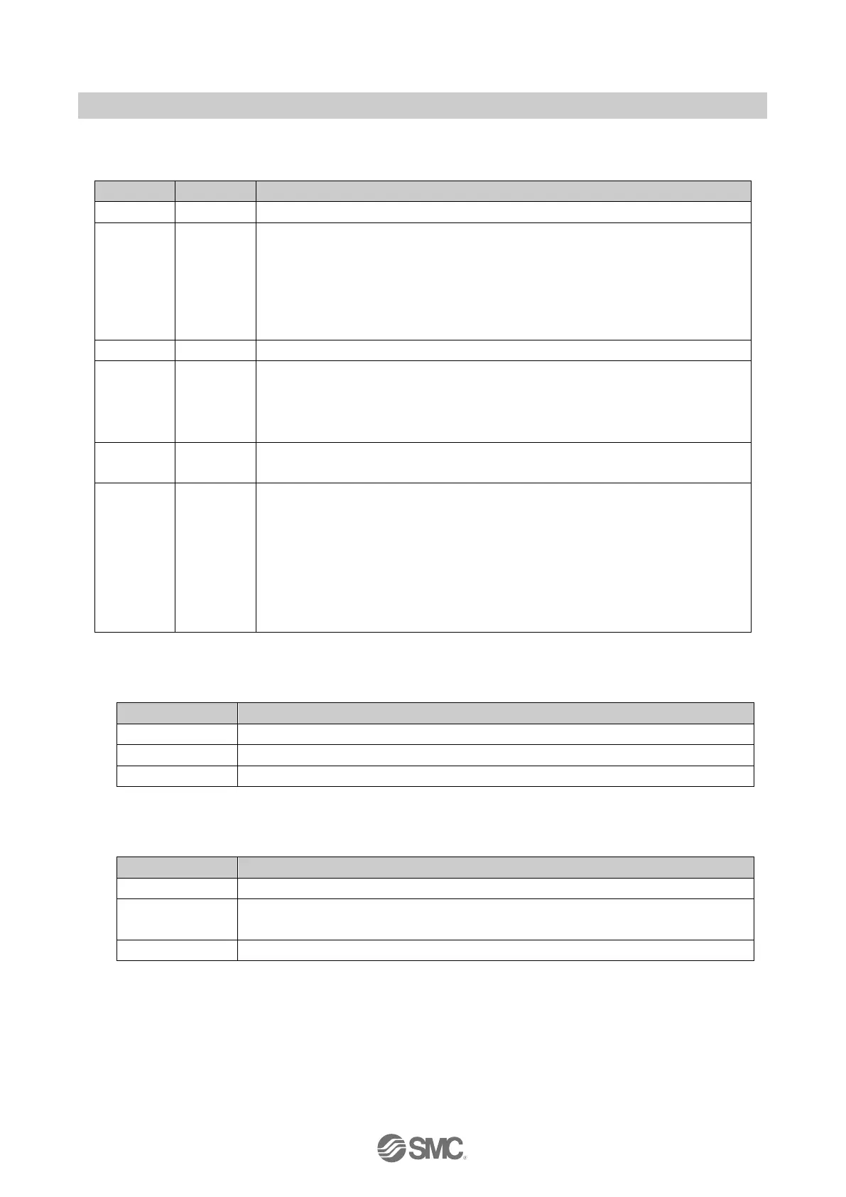
Table 10-19 SF and BF indicators
No fault (The SI Unit is currently exchanging data with the Controller without errors.)
Faulty or no connect message frame (although the SI Unit is physically connected to
the bus)
●IO configuration is defective, or before initial commissioning has been done.
●Device name or IP Address is different from the programmed setting.
●The GSD file is not correct.
●The IO Controller is defective
No IO Controller on the bus.
PROFIsafe communication is not established due to the following reason(s).
●The SI unit is not parameterised by the Safe Controller.
●The parameterisation is not acceptable.
●The F-address is not matched.
The Safe Controller requests operator acknowledgment
The following diagnostic event occurred.
●No safe communication.
●The configuration data sent by the Controller does not match the actual layout.
●Power supply is not present or is below the dropout level
●At least one valve coil has a short circuit, or at least one connected module has a
short circuit, or the module layout has changed.
●Self-test has failed and a power reset is required.
●An incompatible module is connected to the SI Unit.
10.9.1.2. US1 indicator
Table 10-20 US1 indicator
US1 is not present or is below the dropout level (< approx. 17 VDC).
US1 is below the permissible level but above the dropout level (17 to 20.4 VDC).
US1 is present (> approx. 21.6 VDC).
10.9.1.3. US2 indicator
Table 10-21 US2 indicator
US2 is not present or is below the dropout level (< approx. 17 VDC).
US2 is below the permissible level but above the dropout level
(17 to 21.6 VDC).
US2 is present (> approx. 22.8 VDC).
: If the US2 power supply is not present or below the dropout level, the SF LED will also flash and the error code "0x01F1" will be
generated.
To clear the error -
Step 1 Turn on the US2 power supply.
Step 2 For module passivation mode send a reset signal to ACK_REI (Acknowledgement for
Reintegration).For channel passivation mode use the Function Block FB60.

 Loading...


