2.1 SPATIAL MOVEMENT - COORDINATE SYSTEM
Mounting offsets for the SMC Motion sensor in the roll, pitch and Z axis can be set in the SMC IMU
configuration software to compensate for physical alignment errors in the installation. For optimum
performance align the motion sensor physically as accurate as possible before setting up offsets
electronically.
Note: The Z-axis offset is used to compensate for a physical misalignment in the Z-axis mounting
and is not used to set the yaw angle output in the motion sensor.
An improper Z-axis rotation will rotate the coordinate system and will induce roll motion readings
in the pitch axis and the vice versa.
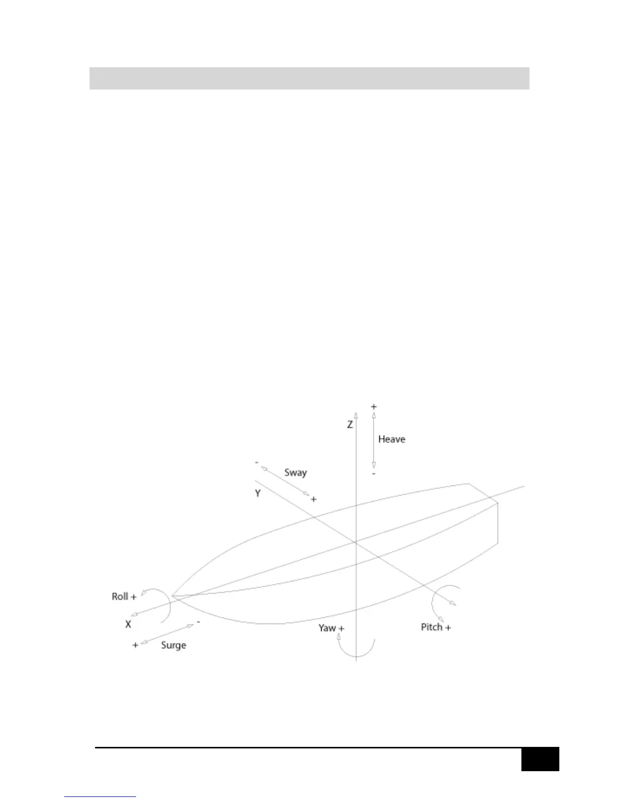
The SMC IMU default rotational and acceleration directions are defined in the drawing below. By
setting an offset the motion sensor rotates its coordinate system. From the configuration software it
is possible to invert the axis rotational directions to suit the receiving application.
Roll is the rotation around the longitudinal axis, X, the axis running from the bow to the stern of the
vessel.
Pitch is the rotation around the transverse axis, Y, the axis running from starboard to port of the
vessel.
Yaw is the rotation around the vertical axis, Z
Shown in the figure below:
 Loading...