-19-
PS##-OMM0003-A
■Wiring
○Connection
•Connections should only be made with the power supply turned off.
•Use separate routes for the Pressure switch wiring and any power or high voltage wiring. Otherwise,
malfunction may result due to noise.
•Ensure that the FG terminal is connected to ground when using a commercially available switch-mode
power supply. When a switch-mode power supply is connected to the product, switching noise will be
superimposed and the product specification can no longer be met. This can be prevented by inserting a
noise filter, such as a line noise filter and ferrite core, between the switch-mode power supply and the
product, or by using a series power supply instead of a switch-mode power supply.
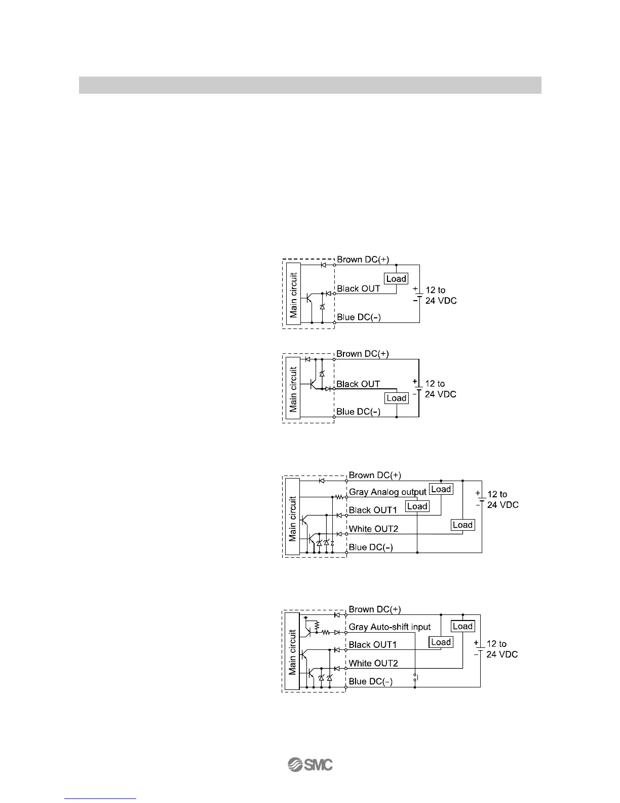
○Internal circuit and wiring example
-N
NPN open collector output type
Max. 28 V, 80 mA
Residual voltage 1 V or less
-P
PNP open collector output type
Max. 80 mA
Residual voltage 1 V or less
-S/-R
(Analog output mode)
Switch output
NPN open collector output type 2 output
Max. 28 V, 8 mA
Residual voltage 1 V or less
R: Analog output 1 to 5 V
Output impedance 1 kΩ
S: Analog output 4 to 20 mA
Max. load impedance
Power supply voltage 12 V: 300 Ω
Power supply voltage 24 V: 600 Ω
Min. load impedance 50 Ω
-S/-R
(Auto-shift input mode)
With auto-shift switch output
NPN open collector output type 2 output
Max. 28 V, 80 mA
Residual voltage 1 V or less
 Loading...