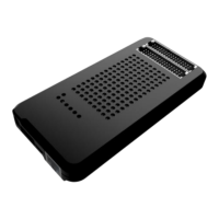
ISP Channel 4: Digital input/output 6 Ground
ISP Channel 4: Digital input/output 7
ISP Channel 4: Digital input/output 7 Ground
ISP Channel 4: Programmable voltage 0
ISP Channel 4: Programmable voltage 0 Ground
ISP Channel 4: Programmable voltage 1
ISP Channel 4: Programmable voltage 1 Ground
ISP Channel 1: Relay Barrier Driver Output
ISP Channel 2: Relay Barrier Driver Output
ISP Channel 1: Relay Barrier Ground
ISP Channel 2: Relay Barrier Ground
ISP Channel 1: Relay Barrier Power Source
ISP Channel 2: Relay Barrier Power Source
ISP Channel 3: Relay Barrier Driver Output
ISP Channel 4: Relay Barrier Driver Output
ISP Channel 3: Relay Barrier Ground
ISP Channel 4: Relay Barrier Ground
ISP Channel 3: Relay Barrier Power Source
ISP Channel 4: Relay Barrier Power Source
Note: Aux connectors are intended to be used only as a development utility.