20
EN
ATYSt - 541995C - SOCOMEC
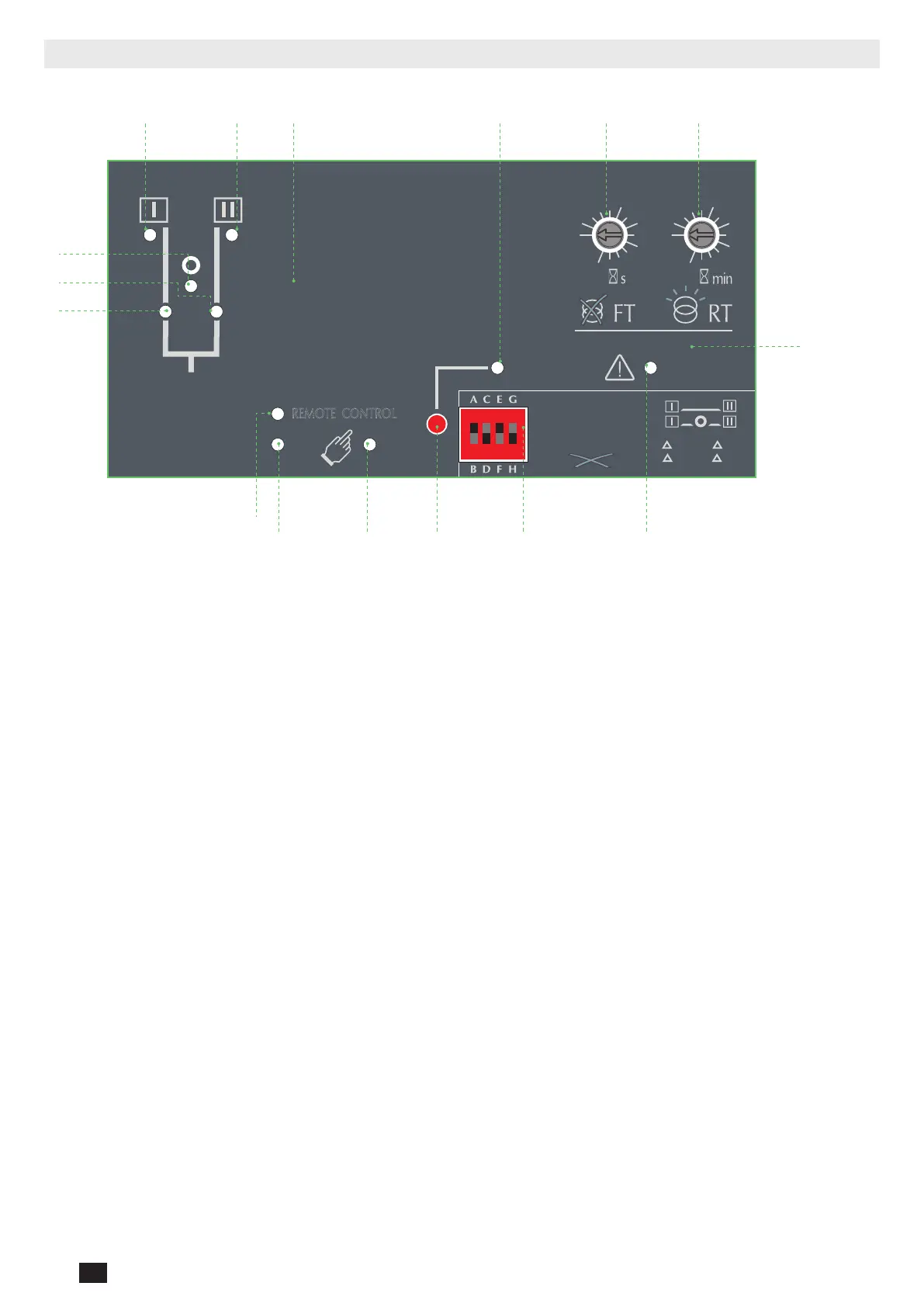
5.3. ATS control module interface
PROG
OK
AUT
READY
0
1
5
10
20
60
0
1
5
10
20
60
G: U
10% F
5%
H:
U
20% F
10%
E:
F:
REMOTE CONTROL
A: 3 Ph
B: 1 Ph
C: Neutral
D: Neutral
Motorised Changeover Switch
ATyS
1600A Ref : 95054160
Un N° PP / PN
1: 220 / 127
2: 380 / 220
3: 400 / 230
4: 415 / 240
5: 480 / 277
6: 208 / 120
7: 220 / 127
8: 230 / 132
9: 240 / 138
10: 380 / 220
11: 400 / 230
12: 415 / 240
13: 480 / 277
5
6
7
8
9
10
11
12
13
14
15
16
18
20
1:
2:
3:
4:
5:
6:
7:
8:
9:
10:
11:
12:
13:
14:
3
3
4
4
5
5
6
6
7
7
8
8
9
10
N°: Δ
U ΔF %
XXX
50 Hz60 Hz
XXXXXXXX
Set Pot
PROG
AUT
Press
60ms
Press
2s
Ready !
PROG
Set Dip
1 2 3
45
PROG
10
111213141516
1
3
2
4 5 6 7 8 9
1. Switch 1 LED position indication (Green when in position I)
2. Switch 2 LED position indication (Green when in position II)
3. Zero position LED indication (Yellow when in position 0)
4. Source supply I availability LED indication (Green when supply I voltage is within the set limits)
5. Source supply II availability LED indication (Green when supply II voltage is within the set limits)
6. Sealing screw location 1 for use with sealing cover (Available as an accessory)
7. READY LED indication
Green steady light : Product in AUTO, Watchdog OK, Product Available to changeover.
Green ashing : Settings displayed not saved or have been changed since last saved.
(Press PROG OK button in manual mode to save or revert to last saved settings).
8. FAILURE Time (FT) Potentiometer to set the supply adjustable from 0 to 60s
9. RETURN Time (RT) Potentiometer to set the supply adjustable from 0 to 60min
10. Sealing screw location 2 for use with the sealing cover.
11. FAULT LED indication.
Red steady light in case of an ATS controller internal fault and blinking in case of an external fault
(rotation incorrect / neutral position incorrect)
Switch the product from Auto to Manual and back to Auto to reset a fault condition.
12. Conguration dip switches
4 dip switches with 2 positions in each
13. PROG OK: Conguration save push button.
ATTN: Active in Manual Mode ONLY
Press briey to conrm and save all set conguration settings.
Hold pressed for 2 seconds to set the network supply voltage and frequency by Auto Conguration.
This is to be followed by pressing briey to save the set value congured (see «8.3. Programming», page 56).
14. MANUAL Mode LED indication
Yellow steady light when in Manual Mode
15. AUTO Mode LED indication
Green steady light when in Auto mode with no timers running.
Green ashing light when in Auto with timers running in the background.
16. REMOTE CONTROL Mode LED indication.
Yellow steady light when in remote control mode.
Remote control mode is achieved with the Auto/Manu selector switched to Auto and terminals 312 closed with terminal
317. Remote control orders are received through closing 314 to 316 with 317.

 Loading...


