51
EN
ATYSt - 541995C - SOCOMEC
Voltage
Sensing
Source II
1Ph / 3Ph
(0 - 332 / 575
Vac)
Voltage Sensing
Source I
1Ph / 3Ph
(0 - 332 / 575
Vac)
Dual auxiliary supply:
Uc 208-277V~ +/-20% 50/60Hz
Power comsumption: 22VA
See instruction sheet
ATS CONTROLLER
To D10
To D20
64B 63B
64B 63B
417 416 415 414 413
207 208 209 210
417 416 415 414 413
207 208 209 210
7172 74
7172 74
ATyS t
Dual auxiliary supply:
Uc 208-277V~ +/-20% 50/60Hz
Power comsumption: 22VA
See instruction sheet
ATS CONTROLLER
ATyS p
Dual auxiliary supply:
Uc 208-277V~ +/-20% 50/60Hz
Power comsumption: 22VA
See instruction sheet
ATS CONTROLLER
ATyS g
Dual auxiliary supply:
Uc 208-277V~ +/-20% 50/60Hz
Power comsumption: 22VA
See instruction sheet
ATS CONTROLLER
To D10
To D20
64B 63B
64B 63B
417 416 415 414 413
207 208 209 210
417 416 415 414 413
207 208 209 210
7172 74
7172 74
ATyS t
Dual auxiliary supply:
Uc 208-277V~ +/-20% 50/60Hz
Power comsumption: 22VA
See instruction sheet
ATS CONTROLLER
ATyS p
Dual auxiliary supply:
Uc 208-277V~ +/-20% 50/60Hz
Power comsumption: 22VA
See instruction sheet
ATS CONTROLLER
ATyS g
7/8 - 103
5/6 - 104
3/4 - 105
1/2 - 106
1/2 - 203
3/4 - 204
5/6 - 205
7/8 - 206
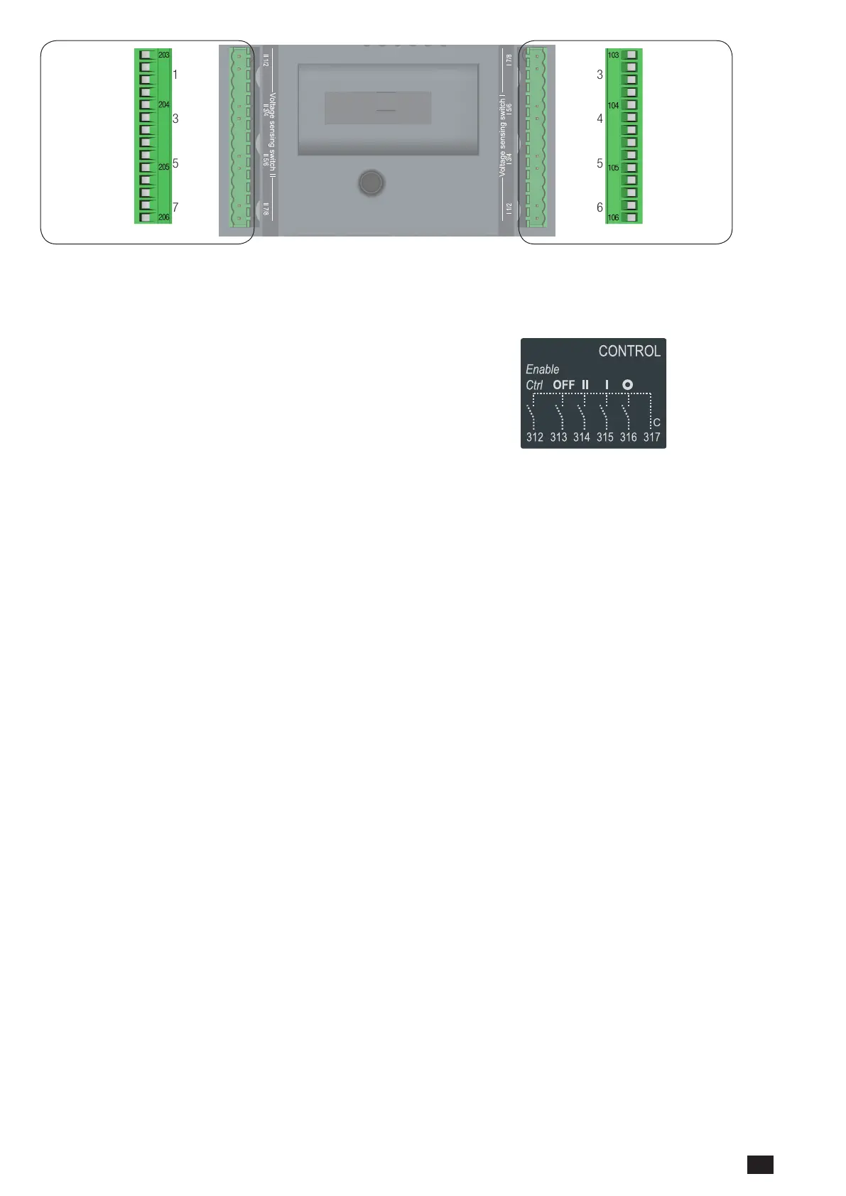
8.2.3. Fixed inputs
8.2.3.1. Description
The ATySt includes for 5 off inputs through a 6 pin connector installed on
the motorisation module. No additional power supply should be used on
these contacts as the inputs MUST be used with the common supply taken
from terminal 317.
The ATySt also includes 4 additional inputs on the ATS Control Module.
Again no additional power supply should be used on these contacts as the
inputs MUST be used with the common supply taken from terminal 417. At
least one of the ATySt aux power supplies (101 – 102 or 201 - 202) must be
available to activate inputs 312 to 317 and 413 to 417.
Pulse duration for activation of contact inputs: ≥ 60ms.
• Pin312:Remote Control Mode Enable when closed with 317.
This contact must be closed with 317 so as to activate all control inputs except for 313 that takes priority and is active
immaterial of the state of input 312. Enabling remote control through 312 activates the remote control inputs whilst
inhibiting the ATS module automation.
• Pin313: Position 0 order if closed with 317 when in AUTO. (Force the switch to the OFF Position)
This is a “Priority Order Input” meaning that when closed with 317 it takes priority over all other electrical commands.
The ATySt will remain in 0 position as long as the contact 313 – 317 remains closed. Once the contact is open the
ATySt is ready to receive new orders. This contact order is independent of other inputs and is also enabled without 312
connected to 317. Impulse duration to activate and start switching to position O is a minimum of 60ms. The product
state will be unavailable.
• Pin314: Position II order if closed with 317.
This contact is active with the ATySt in AUT mode with contact 312 – 317 closed and 313 – 317 open. Impulse
duration to activate and switch to position II is a minimum of 60ms.
• Pin315:Position I order if closed with 317
This contact is active with the ATySt in AUT mode with contact 312 – 317 closed and 313 – 317 open. Impulse
duration to activate and switch to position I is a minimum of 60ms.
• Pin316:Position 0 order if closed with 317
This contact is active with the ATySt in AUT mode with contact 312 – 317 closed and 313 – 317 open. Impulse
duration to activate and switch to position O is a minimum of 60ms. For contactor logic maintain contacts on between
terminal 316 and 317.
• Pin317: Common
Common supply for inputs 312 to 316
• Pin413: Input I1, With / Without Priority
PRI - Activate / deactivate source supply priority when closed or opened with 417. With the contact open the ATySt will
by default set the ATS logic as operation with priority. When closed with 417 the ATySt will operate without priority. The
priority by default is SI however this may be set to SII by the user by closing 414 - 417.
• Pin414: Input I2 , Set Priority Source Supply
This input contact is used to set the priority source supply to SI or to SII. By default and with contacts 414-417 open
the priority supply is set to SI. When 414 is closed with 417 priority is set to SII.
Attn: this input is active with contacts 413 – 417 open.

 Loading...


