ITALIANOENGLISH
56
IOMMASIPXX09-GB 04
10-40 kVA
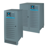
MASTERYS IP+
MASTERYS IP+ allows both parallel power and parallel 1+1 redundant con gurations.
WARNING!
Parallel power con guration is possible ONLY with the transformer connected in the input (Mains
or Auxiliary Mains).
WARNING!
Parallel with transformer connected to the output is possible only by using the speci c kit
including two speci c UPS (one with transformer and one without transformer) for 1+1 redundant
con guration.
WARNING!
Parallel con guration must only be activated by SOCOMEC UPS quali ed personnel.
Use the UPS in accordance with the technical speci cations given in this Installation and Operating Manual.
The UPS units connected in parallel con guration are identical to a standard UPS, as a result safety, shipping and
installation recommendations in chapters 2 and 3 also apply.
INSTALLATION.
• Parallel power con guration:
Please check that the transformer is connected on the input side (Mains or Aux Mains - refer to paragraph 3.5).
UPS units operating in parallel are interconnected using control cables and are con gured di erently depending
on the position they are assigned. For this reason the units have a position label:
• The “LEFT” label means that the unit must be positioned to the left.
• The “RIGHT” label means that the unit must be positioned to the right.
• The “INTERNAL” label (used only on systems with three UPS) means that this unit must be positioned between
the two other cabinets.
• Parallel 1+1 redundant con guration:
UPS units operating in parallel 1+1 redundant con guration are interconnected using control cables and are
con gured di erently depending on the position they are assigned. For this reason the units have a position
label:
• The “LEFT” label means that the unit must be positioned to the left (UPS with transformer con gured as concentrator).
• The “RIGHT” label means that the unit must be positioned to the right (UPS without transformer).
The control cables supplied allow a maximum distance of about 3 metres between the UPS units. This gives enough
room for an external battery cabinet to be inserted beside each UPS.
WARNING!
The UPS must be secured to the oor (see paragraph 3.3).
POWER CONNECTIONS.
• The power supply to each unit must be protected as indicated in the table in paragraph 3.4.
• The cross section and length of the input and output cables must be identical for all the units.
• The phase rotation must be the same for all units connected in parallel.
PARALLEL CONFIGURATION