Communication Board
The communication board is located, inside the Synergy Manager and serves as the
communication hub of the inverter.
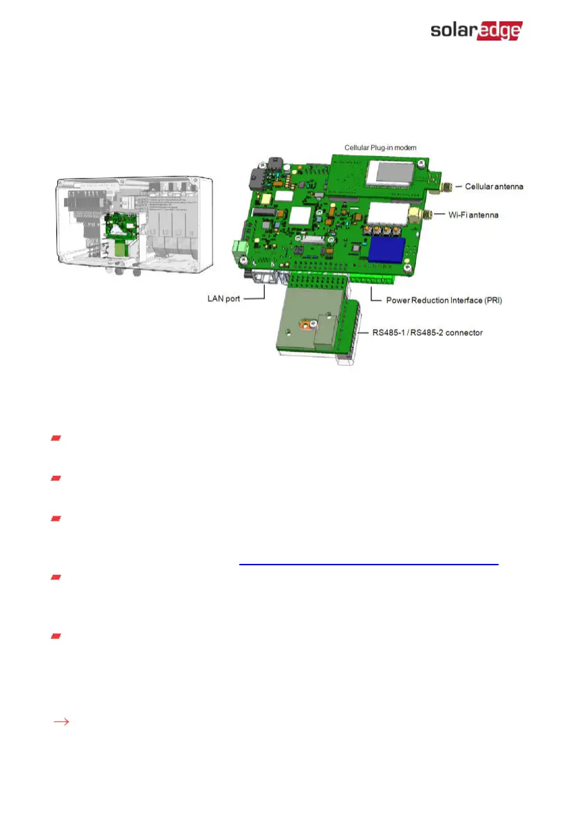
Figure 30: Synergy Manager - communication board
The Communication Board includes the following interface connectors:
Cellular antenna - Antenna port for a Cellular Plug-in modem connecting the
inverter to the internet.
Wi-Fi Antenna - Wireless LAN antenna port for connecting the inverter to an
internet modem
Power Reduction Interface (PRI) - Connecting the Inverter to a power reduction
device, such as a generator.
For more information, refer to: Power Control Configuration - Application Note
RS485-1 / RS485-2 connector - Two Modbus ports for connecting multiple
inverters, over the one line to the Internet. The ports are also used for connecting
peripheral devices such as meters, a batteries and a third party data logger.
LAN port - Ethernet cable port for connecting the inverter to an internet modem
Removing the Synergy Manager Cover
To accsses the communication board, remove the Synergy Manager cover.
To remove the Synergy Manager cover:
1.
Turn OFF the ON/OFF/P switch of the Synergy Manager.
Three Phase Inverters with Synergy Technology PN: SExxK-xxxxIxxxx
64 Communication Connectors
 Loading...


