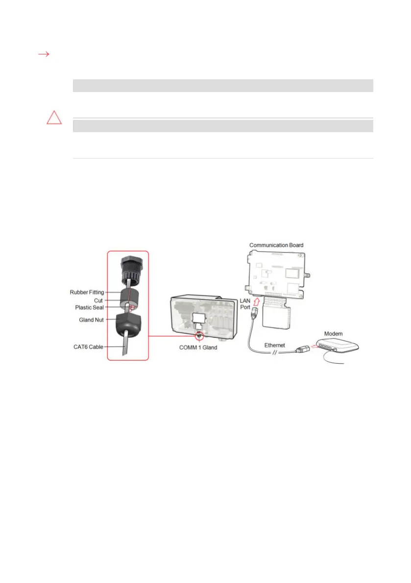
To connect the Ethernet cable:
1. Remove the nut of the COMM1 gland.
CAUTION!
The gland includes a rubber waterproof fitting, which should be used to
ensure proper sealing.
ATTENTION!
Le cote interne du gland contient une rondelle qui doit être utilisée pour une
bonne étancheïté.
2. Insert the CAT6 Ethernet cable through the gland nut.
3. Remove the rubber fitting.
4. Remove the plastic seal from the rubber fitting.
5. Route the LAN cable through the gland opening in the Synergy Manager.
6.
Insert the CAT6 Cable through the cut in the rubber fitting.
Figure 32: Inserting the Ethernet (CAT6) cable
7. Route the Ethernet cable to the communication board and plug to the LAN port.
8. Crimp an RJ45 plug on the Ethernet cable.
9. Tighten the gland nut of 4 lb*ft.
Ethernet (CAT6) Cables
CAT6 cables have eight wires (four twisted pairs), as shown in the pin layout of the
Ethernet connector in
Figure 33
. Wire colors may differ from one cable to another. You
can use either wiring standard, as long as both sides of the cable have the same pin-out
Chapter 5: Setting Up Communication with the Monitoring Platform67
Three Phase Inverters with Synergy Technology PN: SExxK-xxxxIxxxx
 Loading...


