and color-coding.
RJ45 Pin #
Wire Color
(1)
10Base-T Signal
100Base-TX Signal
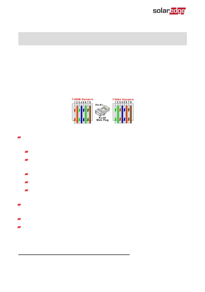
T568B T568A
1 White/Orange White/Green Transmit+
2 Orange Green Transmit-
3 White/Green White/Orange Receive+
4 Blue Blue Reserved
5 White/Blue White/Blue Reserved
6 Green Orange Received-
7 White/Brown White/Brown Reserved
8 Brown Brown Reserved
Figure 33: Ethernet connector - pin layout
Use a non-crimped cable to connect via the gland to the RJ45 port on the inverter's
communication board or, if using a spool of cable, connect as follows:
Insert the cable through the gland.
Remove the cable’s external insulation using a crimping tool or cable cutter and
expose eight wires.
Insert the eight wires into an RJ45 connector, as shown in
Figure 33
.
Use a crimping tool to crimp the connector.
Connect the Ethernet connector to the RJ45 port on the communication board
as shown in
Figure 32
.
For the switch/router side, use a pre-crimped cable or use a crimper to prepare an
RJ45 communication connector.
Connect the cable RJ45 connector to the RJ45 port of the Ethernet router or switch.
You can connect more than one inverter to the same switch/router or to different
switches/routers, as needed. Each inverter sends its monitored data independently
to the SolarEdge Monitoring platform.
(1)
The connection does not support RX/TX polarity change. Supporting crossover Ethernet cables
depends on the switch capabilities.
Three Phase Inverters with Synergy Technology PN: SExxK-xxxxIxxxx
68 Creating an Local Area Network (LAN) Connection
 Loading...


