Chapter 1: Introducing the SolarEdge Control and Communication Gateway
Control and Communication Gateway Installation Guide - MAN-01-00132-1.2
LCD and LCD-Menu Buttons
The LCD screen displays status information of the SolarEdge gateway and various menus for configuration
options. The LCD panel and buttons are used during the following processes:
Operational Mode: The LCD panel allows checking that the gateway is working properly. Refer to
Status Screens on page 32 for a description of this option. Use the LCD user buttons to toggle
through the informative displays and select options.
Setup: After mounting the gateway, the installer may perform basic gateway configuration, as
described in Setup Menu Options on page 35.
Four buttons are used for controlling the LCD menus (see Figure 3):
Esc: Moves the cursor to the beginning of the parameter, goes to the previous menu and cancels a
value change.
Up (1), Down (2): Moves the cursor between menu options, moves among the characters of a
parameter, and toggles between possible characters when setting a value.
Enter (3): Selects a menu option or accepts a value change. Also used to enable LCD backlight.
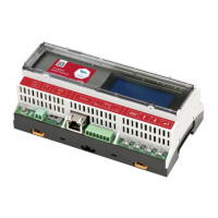
LEDs
The front of the SolarEdge gateway has an LCD panel and three LEDs, as shown above:
The gateway has three LED indicators, as follows:
Power OK (Green): Indicates whether or not the SolarEdge gateway is connected to power
Communication (Yellow): This LED blinks when monitoring information is received from another
SolarEdge device in the installation.
Fault (Red): Indicates that there is an error. For more information, contact SolarEdge support.
All LEDs are ON while the SolarEdge gateway is being configured and during power up.
Communication Connectors
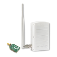
Antenna1: used for optional wireless ZigBee or Wi-Fi antenna connection (refer to Wireless ZigBee
Connection and Wi-Fi Connection on page 45.
Antenna2: Currently not installed
RS485-1 and RS485-2: used for connecting external devices to the gateway (refer to Chapter 3:
Connecting the SolarEdge Gateway to the SolarEdge Installation on page 15)
RS232: enables connection of the SolarEdge gateway to an external device using an RS232 interface.
USB: Enables PC/laptop connection for using the SolarEdge configuration tool.
Ethernet: enables connecting the SolarEdge gateway to the SolarEdge monitoring portal through an
Ethernet switch/router (refer to Creating an Ethernet (LAN) Connection on page 42). The Ethernet
switch/router should be connected to the Internet.