Chapter 1: Introducing the SolarEdge Control and Communication Gateway
Control and Communication Gateway Installation Guide - MAN-01-00132-1.2
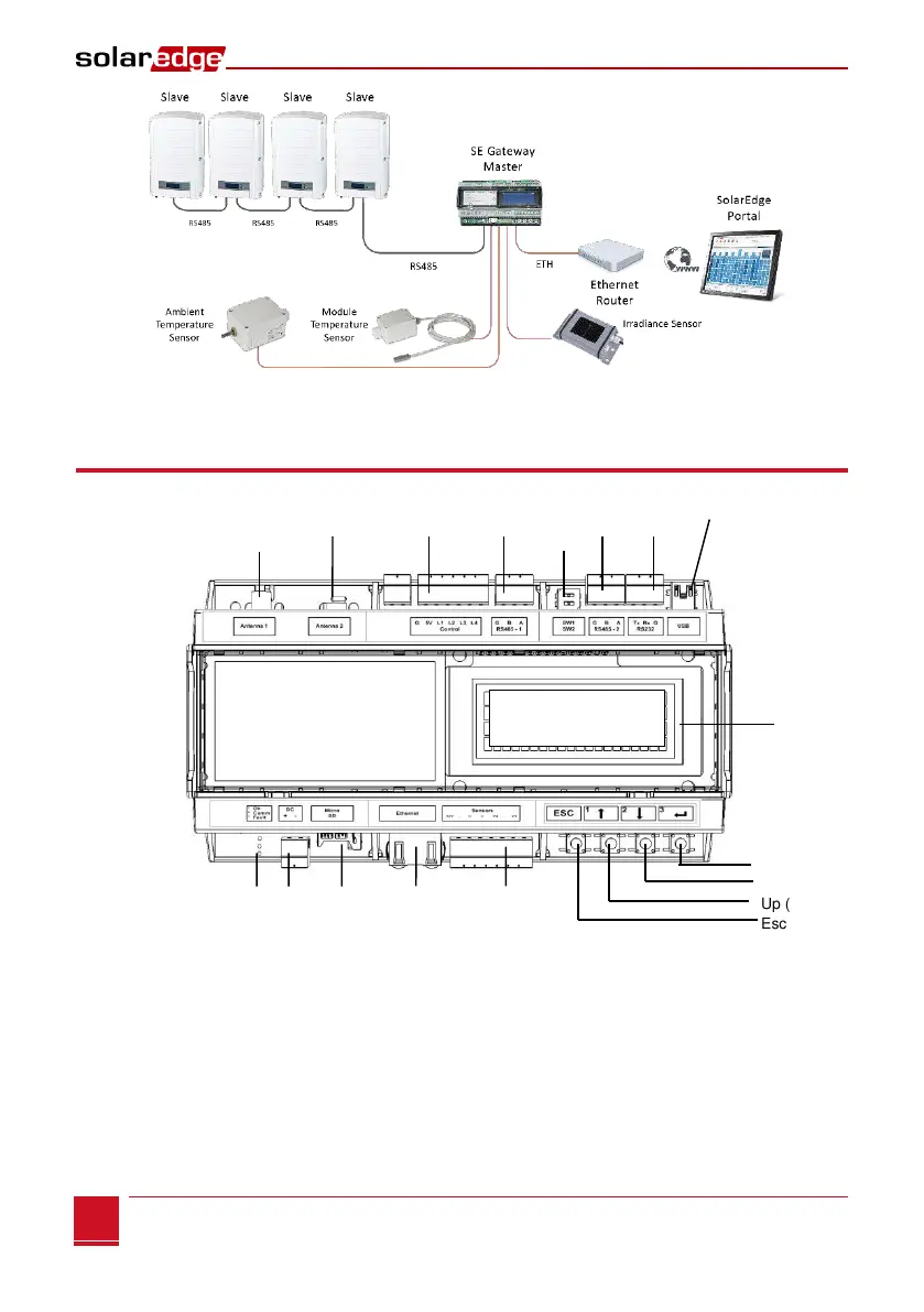
Figure 2: Example of sensor connection to the SolarEdge gateway
Control and Communication Gateway Interfaces
Figure 3: Control and Communication Gateway Interfaces
LEDs: DC Micro SD Ethernet Sensors
Green (power
Yellow supply
Optional Optional
Antenna1 Antenna2 Control RS485-1 SW1 RS485-2 RS232 USB
(ZigBee) SW2