Chapter 3: Connecting the SolarEdge Gateway to the SolarEdge Installation
Control and Communication Gateway Installation Guide - MAN-01-00132-1.2
Chapter 3: Connecting the SolarEdge
Gateway to the SolarEdge Installation
Overview
The SolarEdge control and communication gateway connects to the PV system installation using the RS485
communication option. The RS485 option enables creating a chain (bus) of up to 31 slave SolarEdge
devices, connected to one master, which can be another SolarEdge device or the SolarEdge control and
communication gateway.
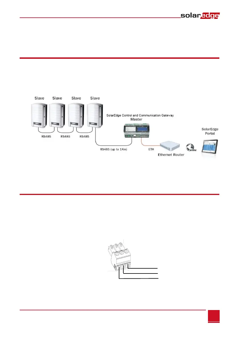
The following is an example of a master gateway connected to a chain of slave inverters.
Figure 5: Example of RS485 connection
The following sections describe how to connect the RS485 bus and how to configure its components.
Connecting and Configuring the RS485
The RS485 bus uses a three-wire cable connecting the RS485-1/2 terminal blocks on the SolarEdge
gateway to the RS485 input of the inverters/SMI.
► To connect the RS485 communication bus between inverters/SMIs and
SolarEdge gateway:
1 Use one of the supplied 3-pin terminal blocks: Loosen the screws and insert the wire ends into the
A, B and G pins. For connections longer then 10m use twisted pair wires for A and B wires.
Figure 7: 3-pin terminal block