Chapter 6: Setting Up Monitoring through the Gateway (Optional)
Control and Communication Gateway Installation Guide - MAN-01-00132-1.2
Set DHCP <En>: If the LAN connection between the gateway and the SolarEdge Monitoring Portal has
a DHCP server, enable this option by setting it to Enable (default). If this option is enabled, then the
DHCP server automatically configures the IP, Subnet Mask, gateway and DNS. If not, set them
manually.
Set IP: Enables setting the IP of the gateway according to the LAN settings:
Use the Up and Down buttons to adjust the value of each IP address octet.
Press the Enter button to move to the next IP address octet.
Long press the Enter button (until Applied message appears) – apply the value
Long press the Esc button (until Aborted message appears) – erase all characters
S e t u p I P
1 9 2 . 1 6 8 . 2 . 7
Set Mask: Set the subnet mask of the SolarEdge gateway according to the LAN settings.
Set Gateway: Set the gateway address of the SolarEdge gateway according to the LAN settings.
Set DNS: Set the DNS of the SolarEdge gateway according to the LAN settings.
Set Server Addr: Set the IP address of the SolarEdge monitoring portal. This option is predefined in
the SolarEdge gateway to specify the SolarEdge monitoring portal IP address and does not normally
need configuration.
Set Server Port: Set the port through which to connect to the SolarEdge monitoring portal. This
option is predefined in the gateway to specify the SolarEdge monitoring portal IP port and normally
does not need configuration.
If your LAN has a firewall, you must verify that the address and port configured in the Set Server
Addr and the Set Server Port fields are not blocked.
You may need to configure it to enable the connection to the following address:
Destination Address: prod.solaredge.com
Port: 22222
Connecting and Configuring LAN
►
To connect the Ethernet port to the router/switch:
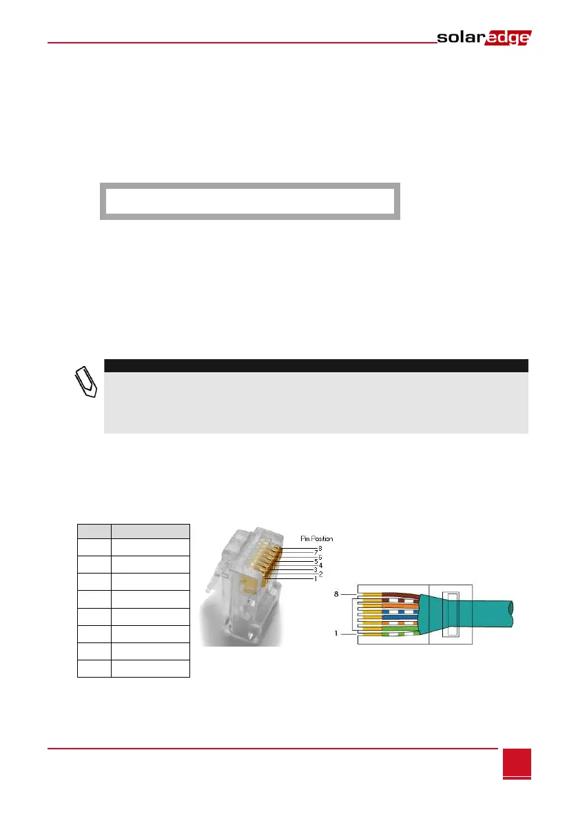
1 Use a pre-crimped cable or use a crimper to prepare an RJ45 communication connector on both ends
of a standard CAT5/6 cable: Insert the eight wires into the RJ45 connector.
Figure 22: Inserting Wires into the RJ45 Connector