Chapter 2: Installing the SolarEdge Gateway
Control and Communication Gateway Installation Guide - MAN-01-00132-1.2
Chapter 2: Installing the SolarEdge Gateway
Safety
For North America only: The product’s communication with external devices, must not use wires
that span more than one building, as per the UL 60950-2 standard.
Transport and Storage
Transport the SolarEdge gateway in its original packaging, without exposing it to unnecessary shocks. If the
original package is no longer available, use a similar box, which can be closed fully.
Store the SolarEdge gateway in a dry place where ambient temperatures are -40°C (-40°F) to
+60°C (140°F).
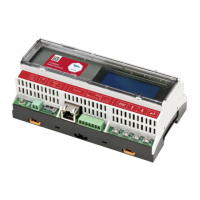
Package Contents
Control and communication gateway
100-240VAC to 12VDC (50 Hz/60 Hz) power supply with an interchangeable AC plug (US,EU,AU)
Accessory kit including:
Three 3-pin terminal blocks
One 7-pin terminal block
One 6-pin terminal block
Installation Equipment
Standard tools can be used during the installation of the SolarEdge gateway. The following is a
recommendation of the equipment needed for installation:
DIN rails
Drill and 4mm diameter bits
Three twisted wires or four-wire twisted pair cable
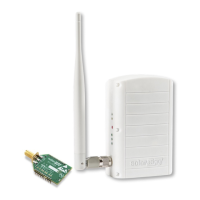
For installing the communication options: CAT5/6 Ethernet cable