Chapter 4: Connecting Environmental Sensors (Optional)
Control and Communication Gateway Installation Guide - MAN-01-00132-1.2
Sensor Connection Example
This section describes how to connect three of the sensors available from SolarEdge to the Control &
Communication Gateway. For their full specifications refer to
http://www.solaredge.com/files/pdfs/products/inverters/se_sensor_datasheet.pdf (for other
recommended sensors and suppliers refer to http://www.solaredge.com/articles/se-supported-
devices#environmental_sensors).
Ambient temperature sensor - a voltage output sensor, measuring the ambient temperature.
Electrical output: 0..10V.
Module temperature sensor - a current output sensor, measuring the module surface temperature.
Electrical output: 4..20 mA.
Solar irradiance sensor - a voltage output sensor, measuring the solar irradiance.
Electrical output: 0-1.4 VDC.
An external 24VDC/1A power supply is required for connecting the temperature sensors. A single PSU can
be used for both sensors.
Use a 3-wire cable for this connection. Recommended wire size is 0.52 mm
2
/ 20 AWG with maximum
length of 50m/164 ft.
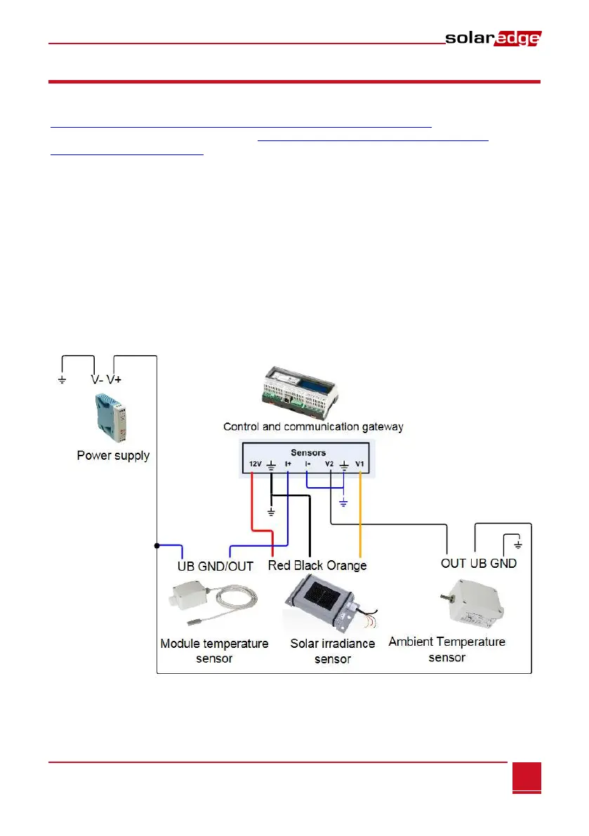
The following diagram illustrates the connections of the above devices to the SolarEdge Control &
Communication Gateway:
Figure 18: Sensors connection diagram