Chapter 4: Connecting Environmental Sensors (Optional)
Control and Communication Gateway Installation Guide - MAN-01-00132-1.2
Connecting Sensors to the SolarEdge Gateway
For connection of the irradiance and temperature sensors available from SolarEdge refer to Sensor
Connection Example on page 29.
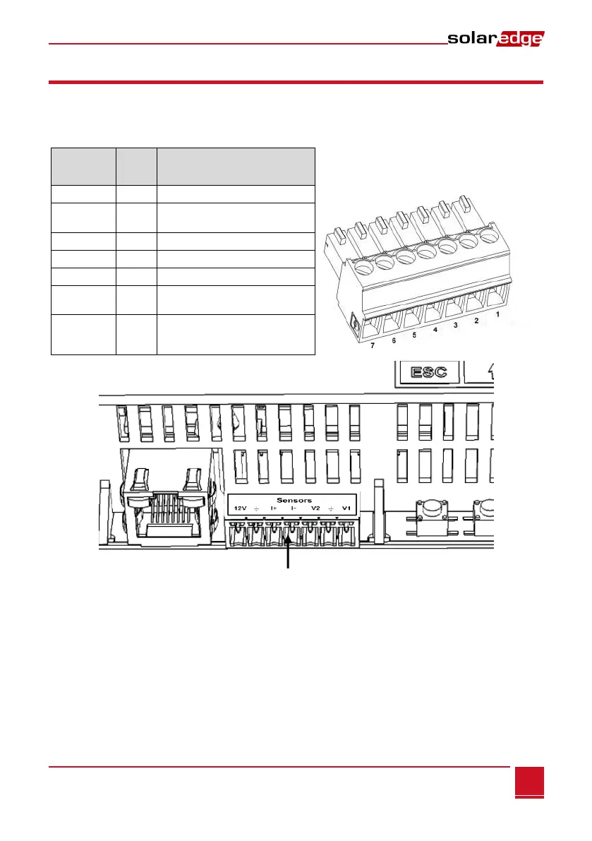
Sensors are directly connected to the SolarEdge gateway via the sensor interface connector. Use the
supplied 7-pin terminal block. Figure 14 shows the location of the sensors connector on the gateway.
Voltage sensor input number 1
Ground (common for V1, V2 and
ground)
Voltage sensor input number 2
Current sensor input – negative
Current sensor input – positive
Ground (common for V1, V2 and
ground)
12VDC output voltage supply to
the sensors. (limited to 800mA)
Figure 14: Sensor Interface Inputs
► To connect a voltage sensor:
Use a 3-wire cable for this connection. Recommended wire size is 0.52mm
2
/ 20 AWG with maximum
length of 50m/164 ft.
1 Connect a voltage source sensor to either V1 or V2, depending on its operating voltage range.
Voltage sensor inputs support the following user selectable ranges:
V1: 0 – 2 Vdc or 0 – 30 mVdc.
V2: 0 – 10 Vdc or 0 – 2 Vdc .
2 Depending on the sensor range, connect the sensor between V1 (pin1) and GND (pin 2), or between
V2 (pin 3) and GND (pin 2).
The GND (pin 2) serves as a common ground for both V1 and V2.