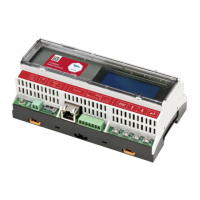
Chapter 5: LCD – Status Screens and Setup Options
Control and Communication Gateway Installation Guide - MAN-01-00132-1.2
Bit 4: The ping to google.com was OK.
Bit 5: The ping to server1 was OK.
Bit 6: The ping to server2 was OK.
Bit 7: The ping to server3 was OK.
Bit 8: Communication to the SolarEdge server is OK.
Error message: Refer to Troubleshooting Ethernet Communication on page 44.
IP Status
This window describes the Ethernet configuration: IP, Mask, TCP gateway and MAC address of the
gateway.
I P 1 9 2 . 1 6 8 . 2 . 1 1 9
M S K 2 5 5 . 2 5 5 . 2 5 5 . 0
G W 1 9 2 . 1 6 8 . 2 . 1
M A C 0 - 27- 02- 00- 39- 36
ZigBee Status
This window describes the ZigBee configuration:
PAN: X X X X X
C H : X X / X X X X R S S I : < L >
ID: X X X X X X X X
Z i g B e e R e a d y
PAN: The ZigBee transceiver pan ID.
CH: The ZigBee transceiver channel
RSSI: The receive signal strength of the neighboring ZigBee transceiver. L = low, M = medium,
H = high and - = no signal.
ID: The ZigBee transceiver ID.
ZigBee Ready: This field is shown only in devices with ZigBee router transceivers (slaves), in a multi-
point (MP) protocol configuration. If a ZigBee transceiver is not physically connected, a No ZigBee
message is displayed.
Wi-Fi Status
This window describes the Wi-Fi configuration:
I P : 1 9 2 . 1 6 8 . 2 . 1 1 9
G W : 1 9 2 . 1 6 8 . 2 . 1
S S I D : x x x x x x x x
R S S I : < L / M / H / - >
IP: The DHCP provided address
GW: The gateway IP address
SSID: Service Set Identifier - the name of a wireless local area network (WLAN). All wireless devices
on a WLAN must employ the same SSID in order to communicate with each other.
RSSI: The receive signal strength indication of the closest Wi-Fi in the SolarEdge system. L = low,
M = medium, H = high and - = no signal.