Chapter 4: Connecting Environmental Sensors (Optional)
Control and Communication Gateway Installation Guide - MAN-01-00132-1.2
The 12V (pin7) can be used as the supply voltage to the sensor. Optionally, an external power
supply can be connected to the sensors if a different input voltage to the sensor is required.
Excessive current on the sensor input can damage the SolarEdge gateway. Refer to input ranges
specified in Appendix A: Technical Specifications on page 46.
Configuring Environmental Sensors
Menus
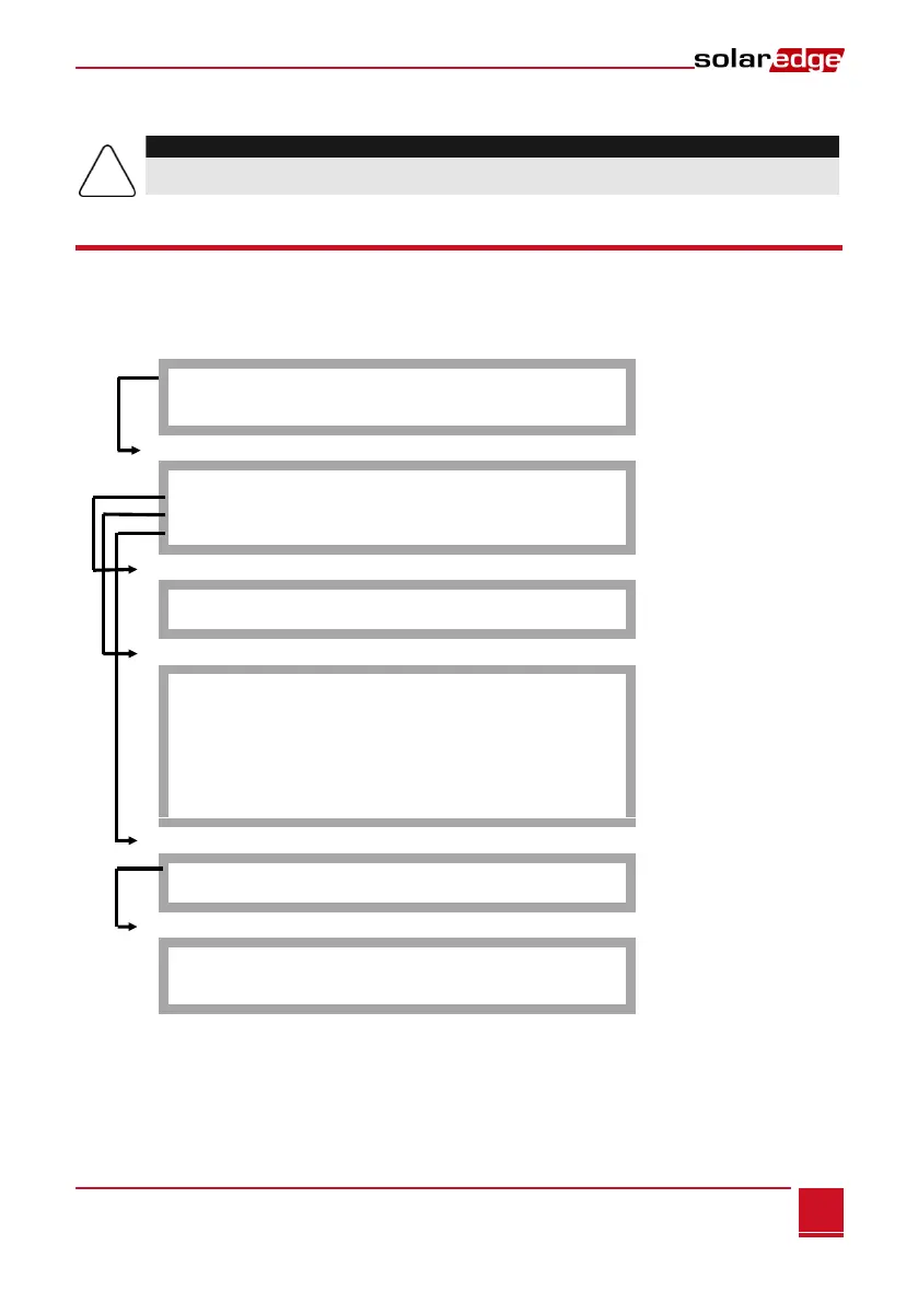
The SolarEdge gateway sensor interface is disabled by default. The following shows a hierarchical tree of
the Sensors menu options:
Sensors
V 1 S e n s o r < D i s >
V 2 S e n s o r < D i s >
I S e n s o r < D i s >
Set V1/V2/I Sensor (example for V1 sensor)
S e n s o r < E n >
R a n g e < 0 - 2 V >
T y p e < - - - >
T w o P o i n t s
Range
0 – 2 V
0 – 3 0 m V
Sensor Type
T e m p . A m b i e n t
T e m p . M o d u l e
W i n d S p e e d
W i n d D i r e c t i o n
I r r a d i a n c e G l o b a l
I r r a d i a n c e D i r e c t
I r r a d i a n c e D i f f .
I r r a d i a n c e P O A
Two Points setting
P 0 < 0 . 0 , 0 . 0 >
P 1 < 1 . 0 0 0 , 1 . 0 0 0 >
Set Point
S e t P o i n t
( V,d e g C )
0 . 0 , 0 . 0
Sensors:
V1 Sensor and V2 sensor- sensors with voltage output, enabled or disabled
I Sensor – a sensor with current output, enabled or disabled
Range:
V1 – select a range between 0 – 2 Vdc or 0 – 30 mVdc.
V2 – select a range between 0 – 10 Vdc or 0 – 2 Vdc.I – select a range between 0 – 20 mA