Chapter 3: Connecting the SolarEdge Gateway to the SolarEdge Installation
Control and Communication Gateway Installation Guide - MAN-01-00132-1.2
2 Choose either RS485-1 or RS485-2 for connection. Connect the 3-pin terminal block to the designated
port on the gateway.
RS485-1 is configured as SolarEdge device by default, therefore RS485-1 is recommended as
the RS485 bus connection point.
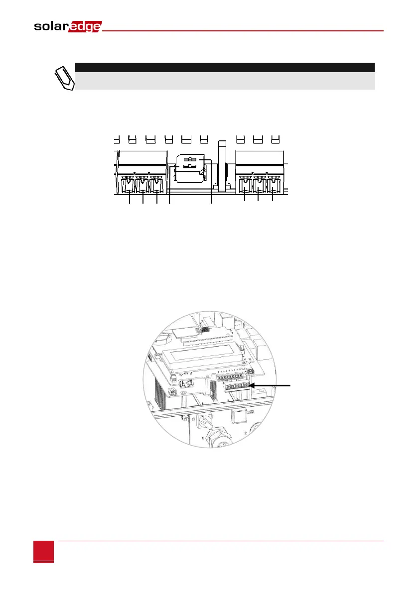
3 If the gateway is at the end of the RS485 chain, terminate the gateway by switching a termination
dipswitch to ON. The switches in the SolarEdge gateway are marked SW1 for the RS485-1 port
termination and SW2 for the RS485-2 port termination, as shown below:
Figure 8: RS485 connectors and termination switches
4 Open the inverter/SMI cover as described in their manual.
5 Remove the seal from one of the openings in communication gland #2 of the inverter and insert the
cable through the opening.
6 Pull out the 9-pin RS485/RS232 terminal block connector, as shown below:
Figure 9: The RS485/RS232 terminal block in the inverter/SMI