Chapter 3: Connecting the SolarEdge Gateway to the SolarEdge Installation
Control and Communication Gateway Installation Guide - MAN-01-00132-1.2
7 Loosen the screws of pins B, A and G on the left of the RS-485 terminal block:
For inverter: RS485-1 pins (left-most)
For SMI: RS485-1 (recommended, as this is the default configuration), or RS485-2
Figure 10: RS485/RS232
8 Insert the ends of wires into the G, A and B pins shown above. You can use any color wire for each of
the A, B and G connections, as long as the same color wire is used for all A pins, the same color for all
B pins and the same color for all G pins.
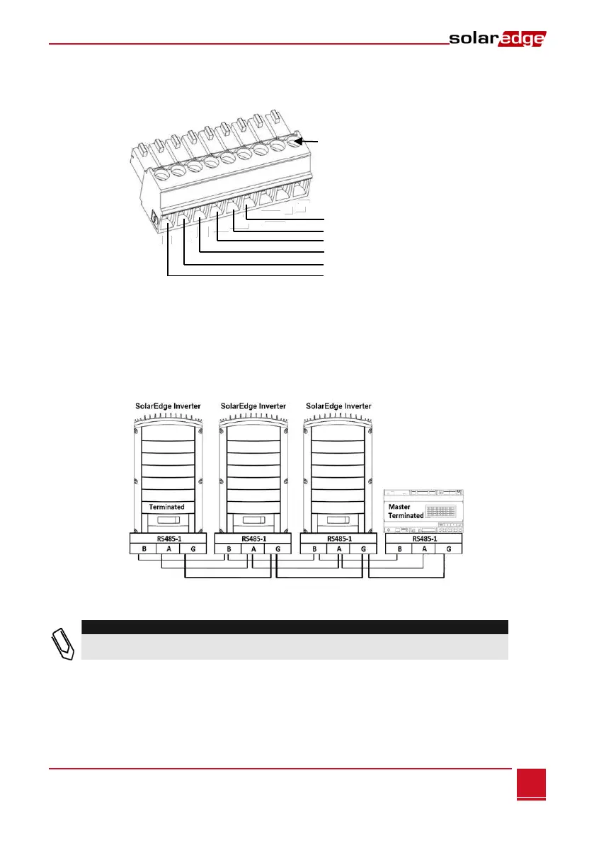
9 Connect all B, A and G pins in all inverters/SMI. The following figure illustrates this connection
schema (the illustration applies to both inverters and SMI):
Figure 11: Connecting SolarEdge devices (inverters or SMI) in a chain
NOTE:
Do not cross-connect B, A and G wires.
For inverters - Do not insert wires into RS485-2 pins.
RS485-2 (used in SMI only)