EasyManuals Logo

SolarEdge SE5K User Manual

SolarEdge SE5K
94 pages
To Next Page IconTo Next Page
To Previous Page IconTo Previous Page
Page #58 background imageLoading...
Page #58 background image
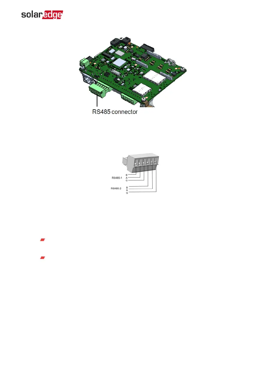
Figure 23: The RS485 terminal block
4.
Loosen the screws of pins A(+), B(-), and G on the left of the RS485 terminal block
(RS485-1 or RS485-2).
Figure 24: RS485 terminal block
5.
Insert the wire ends into the G, A and B pins shown above. Use Four- or six-wire
twisted pair cable for this connection.
You can use any color wire for each of the A, B and G connections, as long as:
The same color wire is used for all A pins the same color for all B pins and
the same color for all G pins
The wire for G is not from the same twisted pair as A or B.
6.
For creating an RS485 bus - connect all B, A and G pins in all inverters. The following
figure shows this connection schema:
Chapter 6: Setting Up Communication 57
Three Phase System Installation Guide MAN-01-00505-1.2

Table of Contents

Questions and Answers:

Question and Answer IconNeed help?

Do you have a question about the SolarEdge SE5K and is the answer not in the manual?

SolarEdge SE5K Specifications

General IconGeneral
ModelSE5K
ManufacturerSolarEdge
AC Output Power5000 W
Rated AC Power5000 W
Max. Efficiency98.3%
CoolingNatural convection
Protection RatingIP65
Max. Input DC Voltage480 V
Max. Input Current11 A
Number of MPP Trackers1
Warranty12 years
Communication InterfacesRS485, Ethernet
AC Voltage230 V
Operating Temperature Range-25°C to +60°C
MPPT Voltage Range330-480V

Related product manuals