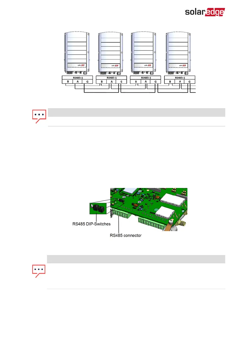
Figure 25: Connecting the inverters in a chain
NOTE
Do not cross-connect B, A and G wires.
7. Tighten the terminal block screws.
8. Check that the wires are fully inserted and cannot be pulled out easily.
9.
Push the RS485 terminal block firmly all the way into the connector on the right side
of the communication board.
10.
Terminate the first and last SolarEdge device in the chain by switching a termination
DIP-switch inside the inverter to ON (move the left switch up). The switch is located
on the communication board and is marked SW7SW1.
Figure 26: RS485 termination switch
NOTE
Only the first and last SolarEdge devices in the chain should be terminated.
The other inverters in the chain should have the termination switch OFF
(down position).
11. If not using surge protection, connect the grounding wire to the first inverter in the
RS485 chain; make sure the grounding wire is not in contact with other wires. For
inverters with a DC Safety Unit, connect the grounding wire to the grounding bus-
bar in the DC Safety Unit.
-Three Phase System Installation Guide MAN-01-00505-1.2
58 Creating an RS485 Bus Connection