using
me biizo/ wun an i-ma
1 INTRODUCTION
This chapter provides
an example on how to set up and run a.c. sweeps, in conjunction
with a Solartron FRA
type
1250, 1254,
1255 or
1260
(1255/60 recommended).
Counter
Electrode
(CE)
Reference
Electrode 1
(RE1)
Reference Working
Electrode
2 Electrode
(RE2)
(WE)
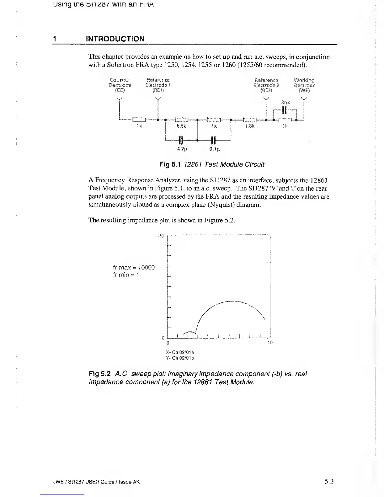
Fig 5.1 12861 Test Module Circuit
A Frequency
Response Analyzer, using the
S11287 as
an interface,
subjects the 12861
Test Module,
shown in Figure
5.1,
to an a.c. sweep. The SI1287 V’
and T on the rear
panel
analog outputs are processed by the FRA and the resulting impedance
values are
simultaneously plotted as a complex
plane
(Nyquist) diagram.
The resulting impedance
plot is shown in Figure 5.2.
10
fr max
=
10000
fr min
-
1
o
o
10
X~
Ch 02/01
a
Y-
Cn
02/01 fa
Fig 5.2 AC. sweep
plot: imaginary impedance component (-b) vs. real
impedance
component (a) for the 12861 Test Module.
JWS
/
S1
1287 USER Guide
/
Issue AK
5.3