Chapter
5
2
HARDWARE
CONNECTIONS: AC SWEEP
Connect the
fout 12861 Test Module terminals to the corresponding SI1287 front panel
sockets
using
the cables supplied. If, however,
a
real cell is
to
be used refer
to the cell
configurations, as detailed in Chapter
2,
section 3.
When
using
the
1255/60 FRA, connect the V OUT, I OUT and POL IN connectors
on the
SI1287 to the
INPUT
V2 HI, INPUT VI HI, and GEN OUTPUT connectors
on the
FRA.
Three one-metre BNC to BNC cables for this purpose are provided
in accessory kit
12871 A. Note that you must also select ‘single-ended’
connections in the Analyzer
input menu. (See Section
3.2.)
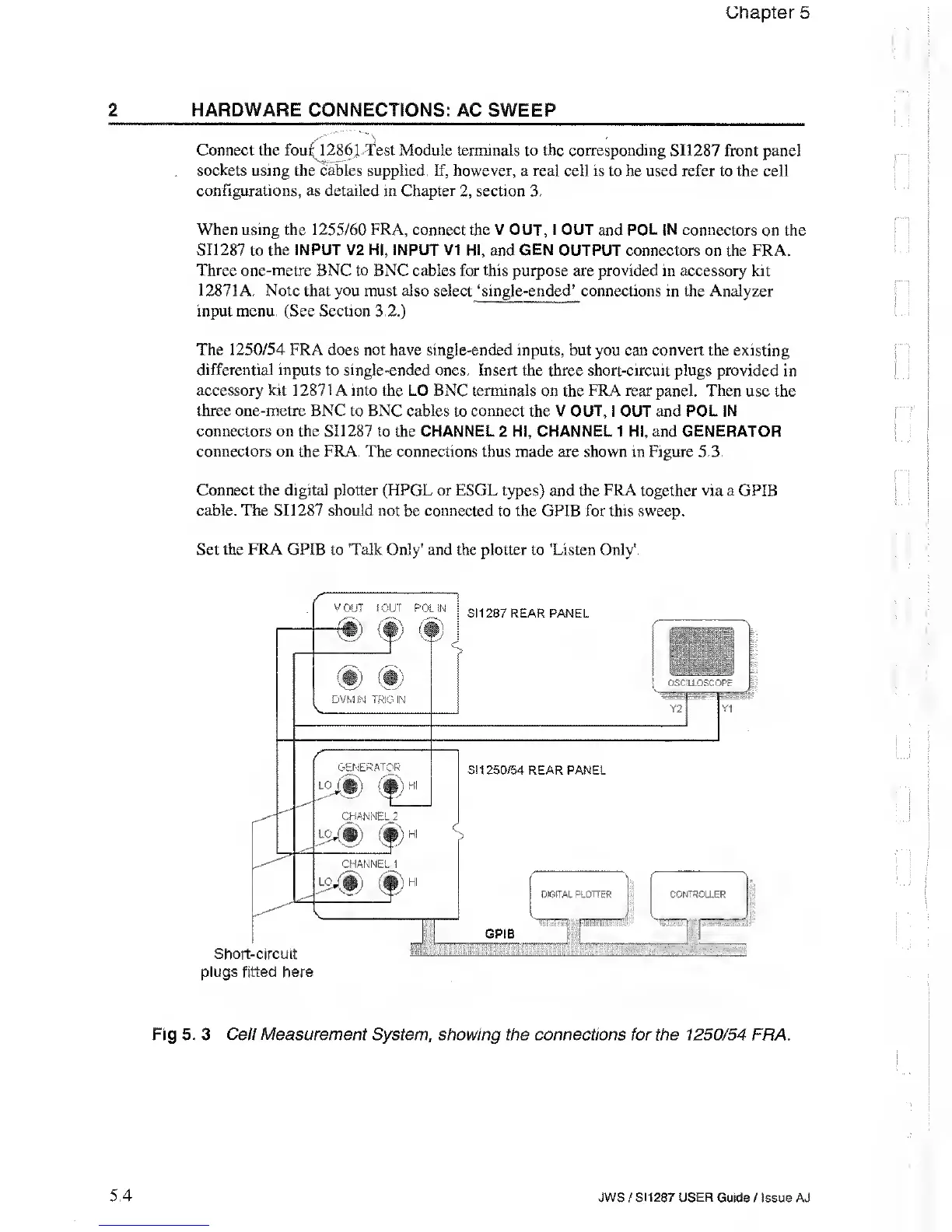
The
1250/54
FRA does not have single-ended inputs, but you can convert the
existing
differential inputs to single-ended ones. Insert the three short-circuit plugs
provided in
accessory kit 12871 A into the LO BNC terminals
on the
FRA rear
panel. Then use the
three one-metre BNC to BNC cables
to
connect
the V
OUT,
I OUT and POL IN
connectors on the SI1287
to the CHANNEL 2 HI, CHANNEL 1 HI, and GENERATOR
connectors on
the
FRA.
The connections thus made are shown in Figure 5.3.
Connect the digital plotter (HPGL or ESGL types)
and
the FRA
together via a GPIB
cable. The SI1287 should not
be
connected
to the GPIB for this sweep.
Set the FRA GPIB to 'Talk Only'
and
the
plotter to
'Listen Only'.
Fig 5. 3 Cell Measurement System
,
showing the connections for the 1250/54
FRA.
5.4 JWS
/
SI1287 USER
Guide / Issue AJ