4 SETTING
PARAMETERS FOR A POTENTIODYNAMIC
POLARIZATION
CURVE
The purpose of this section is to give you a brief
introduction
to the
front
panel
operation; how to set up
parameters, read measurements and plot results. Once
you have achieved this, you will be sufficiently
familiar with the SI1287 to
set up
your own experiments. The 12861 Test Module is used to
simulate the cell.
This exercise will plot current as a
function of swept potential. This sort of plot
provides
a
general overview of corrosion reactions in a wide
potential range
and
is useful for applications
where screening tests of inhibitors, alloying elements,
passivity and electrode kinetics are required.
Section 4.1 details the connections to be made
from the 12861 Test Cell Module
and
the plotter to the SI1287. When the connections have been
made
the
instrument should then be
initialized (section
4.2).
With the instrument in the
default
state
the following parameters will be entered:
{I Measure}, {DVM}, {Sweep}, {Data Output}, and {Plot}. Other
parameters
are left in the
default
state; see
section 4.3.
{I
Measure}
{DVM}
{Sweep}
(Data Output}
(Plot}
sets the current measuring resistor and protection
levels,
set the display parameters,
set the limits for the sweep,
sets the
output
data.
sets
the
parameters for plotting, such as the grid
coordinates,
size of paper, grid on/off, etc.
4.1 EXTERNAL CONNECTIONS
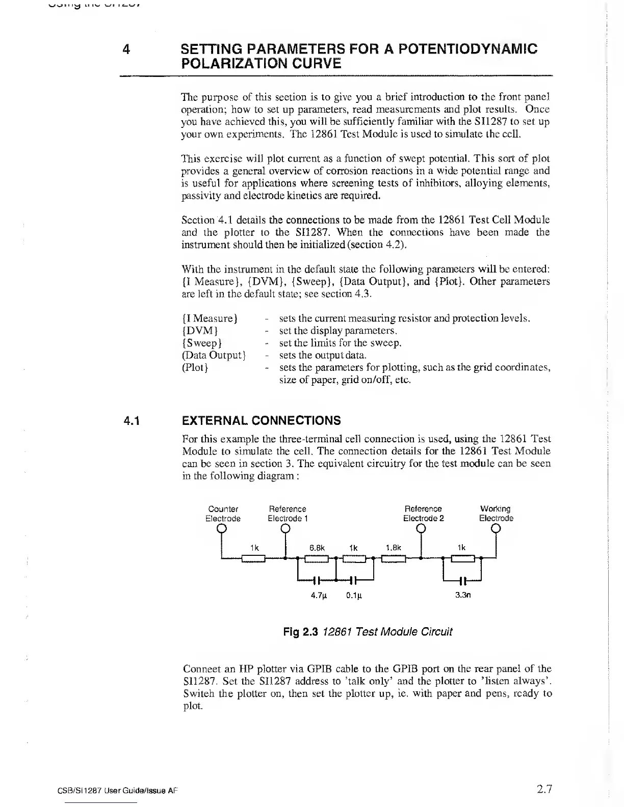
For
this
example the
three-terminal cell connection is used, using the 12861 Test
Module to simulate the cell. The connection details for the
12861 Test Module
can be seen in section 3. The equivalent
circuitry for the test module can be seen
in the following diagram
:
Counter
Electrode
Reference
Electrode 1
Reference
Electrode 2
Working
Electrode
Fig 2.3
12861 Test Module Circuit
Connect an HP plotter via GPIB
cable
to
the GPIB port on the rear
panel
of the
SI1287. Set the SIX
287
address to ’talk only’ and the
plotter
to
’listen always’.
Switch the plotter on, then set the plotter up, ie. with paper and pens,
ready to
plot.
CSB/S11287 User
Guide/Issue AF
2.7