[sampled]
Sampled IR
compensation periodically
interrupts the cell current. During
the current off
time
the IRpdrop disappears
immediately and allows
the double-layer impedance
voltage
(which
decays relatively slowly)
to be sampled and held. The SI1287 feedback
circuit
monitors this voltage and
maintains it at the user-defined polarization
value.
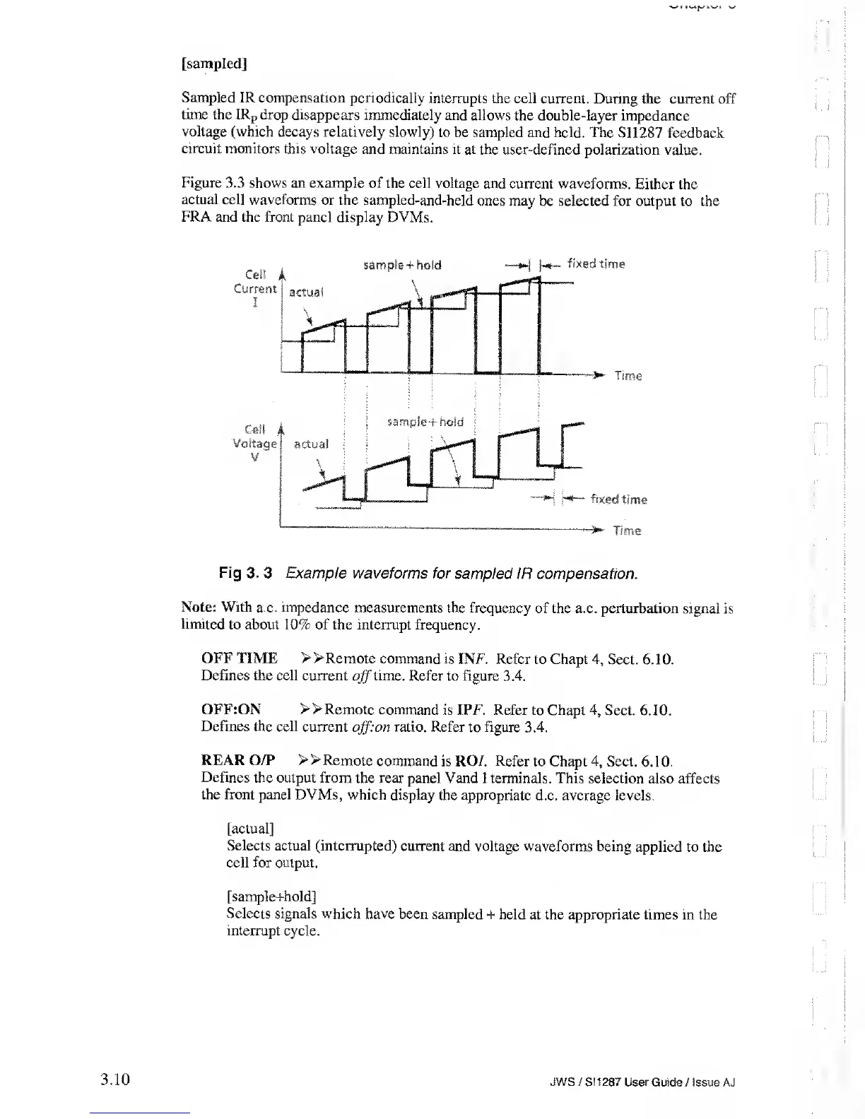
Figure
3.3 shows an example of
the cell voltage and
current
waveforms.
Either the
actual cell waveforms
or the sampled-and-held
ones may be selected for output
to the
FRA and
the front panel display DVMs.
Fig
3.
3 Example waveforms for
sampled IR compensation.
Note: With
a.c. impedance
measurements the frequency
of
the
a.c. perturbation signal is
limited to about 10%
of the interrupt frequency.
OFF TIME >>Remote
command is
INF. Refer to Chapt
4,
Sect. 6.
10.
Defines
the cell current
off
lime.
Refer to figure 3.4.
OFF:ON
»Remote command
is IPF. Refer to Chapt
4,
Sect. 6.10.
Defines
the cell current
offion
ratio. Refer
to
figure
3.4.
REAR
O/P >>Remote
command is ROI. Refer
to Chapt
4,
Sect. 6.10.
Defines the
output from the rear panel Vand I
terminals. This selection also
affects
the
front panel DVMs, which display
the appropriate
d.c.
average levels.
[actual]
Selects actual (interrupted)
current and voltage waveforms
being applied to the
cell for
output.
[sample+hold]
Selects signals which
have been sampled +
held at the appropriate times in
the
interrupt
cycle.
3.10
JWS/SI1287
User Guide /Issue AJ