.CURRENT
ON-
OFF'
k
ON
TIME
«
OFF.*
s
TIME
t
1
H
PERIOD
TIME
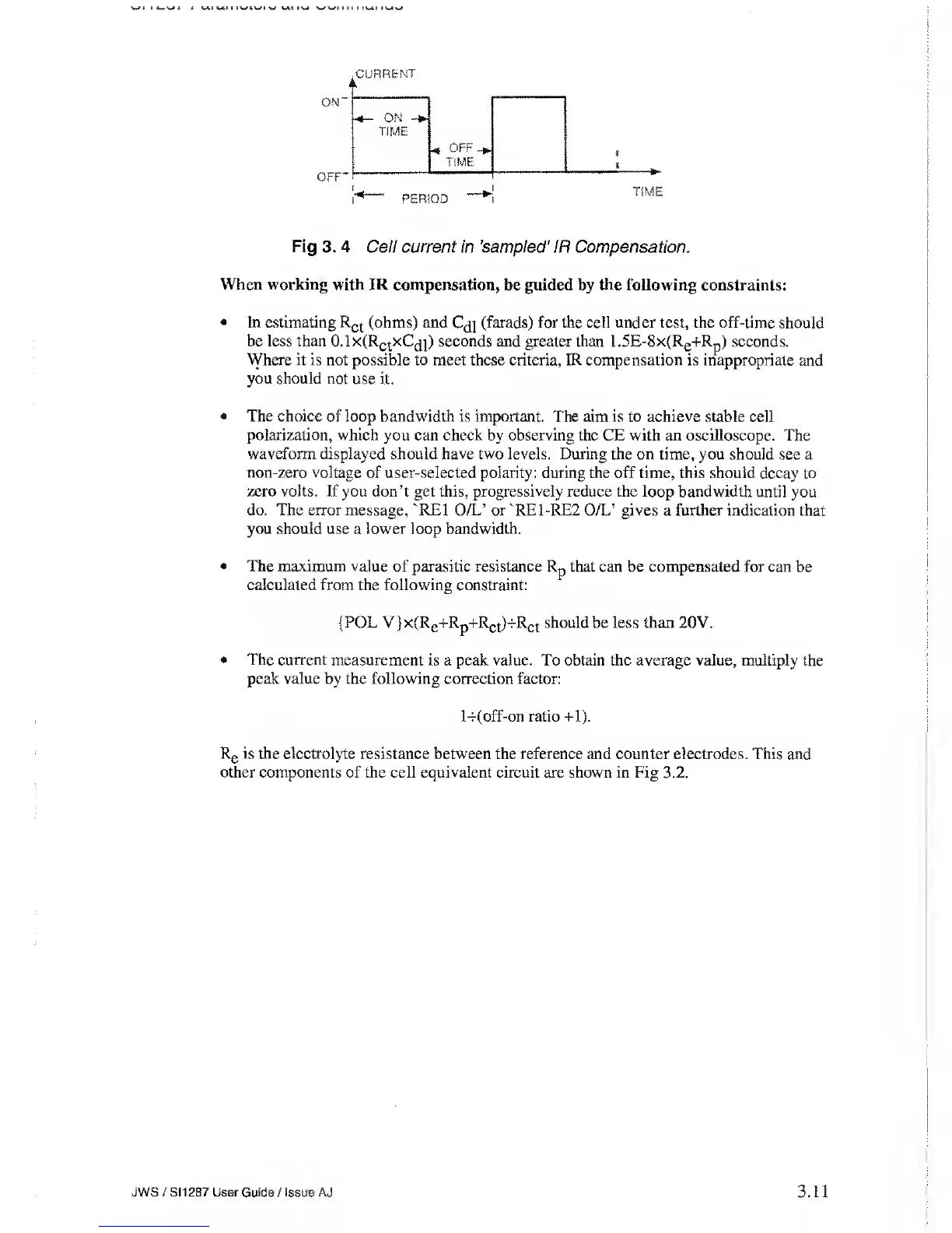
Fig 3. 4
Cell
current in
’sampled’ IR
Compensation.
When
working with IR compensation,
be guided by the following constraints:
•
In estimating R
ct
(ohms) and
C^}
(farads) for the cell under
test, the off-time should
be less than 0.1x(Rq
t
xC
(
j])
seconds and greater than
1.5E-8x(Re+Rp)
seconds.
Where it is not possible to meet these criteria, IR compensation is inappropriate
and
you should not
use it.
•
The choice of loop bandwidth is important.
The aim is to
achieve
stable cell
polarization, which you can check by observing the CE with an oscilloscope. The
waveform displayed should have two levels. During the
on time, you should see a
non-zero voltage
of user-selected polarity: during the off time, this should decay
to
zero volts. If you don’t get this, progressively reduce the loop bandwidth
until you
do. The error message, 'RE1
O/L’ or 'RE1-RE2 O/L’ gives a further indication that
you should use a lower loop bandwidth.
•
The maximum value of parasitic
resistance
Rp that can be compensated
for can be
calculated
from
the
following constraint:
(POL V}x(R
e
+R
p
+R
ct
HR
ct
should
be less
than
20V.
•
The current measurement
is a peak value.
To
obtain the average
value,
multiply the
peak value
by the
following
correction factor:
l-r(off-on ratio
+1).
Rg is the electrolyte
resistance between the reference and counter electrodes. This and
other
components of the cell equivalent circuit are shown in Fig 3.2.
JWS / S1 1 287 User
Guide /
issue AJ
3.11