21
7. Electrical connection
7.4 Additional information on
connections and accessories
Connection overview: see “Connection overview and
DIP switches” on page 47.
Additional configuration options are available for many
accessories via DIP switches and SOMlink.
“DIP switches” on page 24
7.5 SOMlink
SOMlink makes it possible for qualified specialists to
change many functions and settings of the control unit.
These include operating parameters and convenient
functions.
If you would like to make changes, contact your specialist
dealer.
INFORMATION
SOMlink is a combination of an additional
device and a web-based application for
changing control unit functions.
A WiFi-enabled device is required.
Since safety-relevant values can also be
changed,SOMlinkisonlysoldtoqualied
specialists.
All changes to settings via the SOMlink
are logged.
7.6 Mains connection
INFORMATION
► The work steps described here are not
required in the case of initial installation/
initial operation, as they have already been
carried out at the factory.
► Approved wire cross sections for the mains
connection: 1.5 mm²–4 mm².
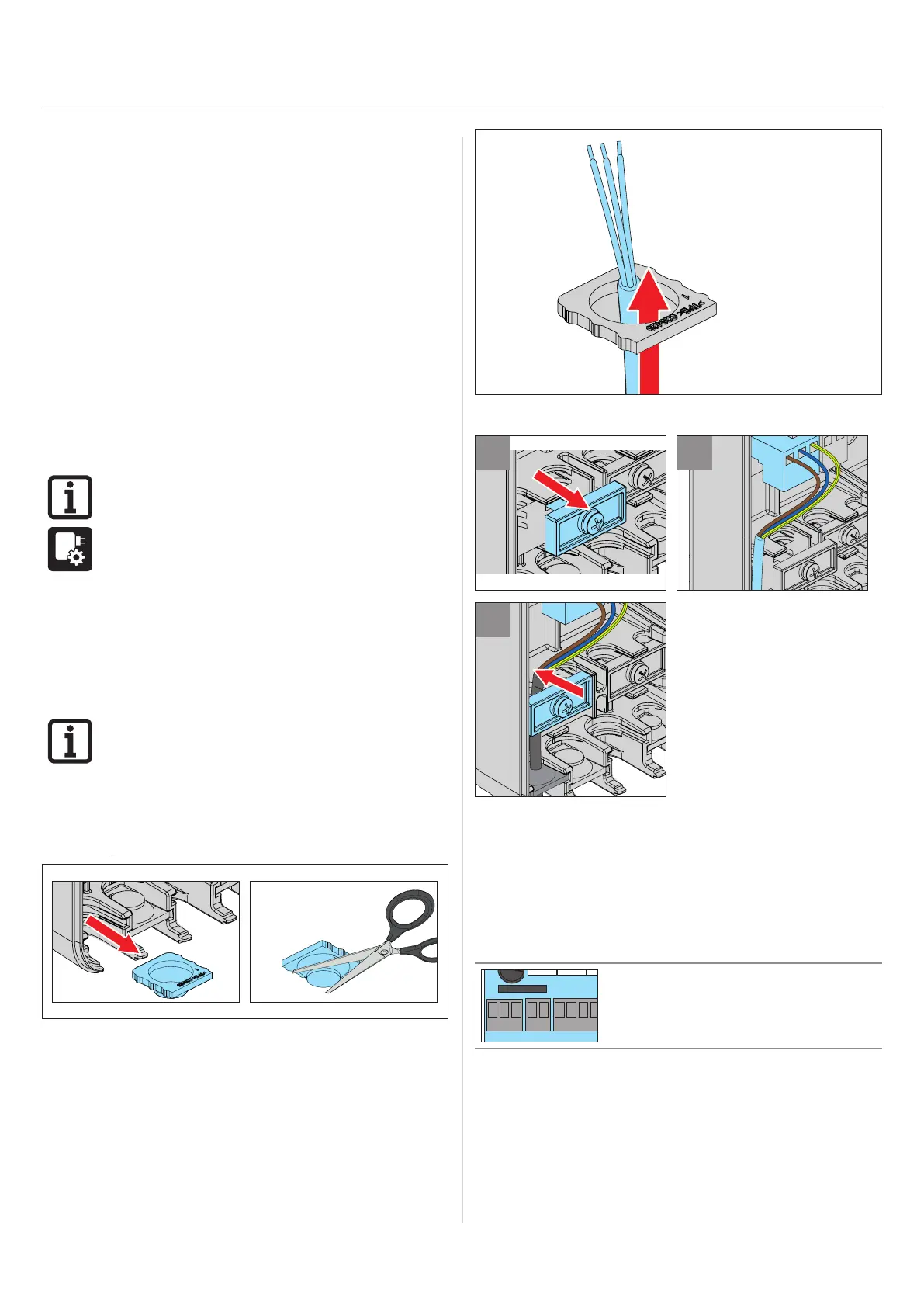
1. Pull out the grommet and create an opening for the
cable.
2. Route the cable through the grommet.
3
4
5
3. Loosen the strain relief.
4. Connect strands to terminals (see connection table).
5. Fasten power cord with strain relief.
Connection table
Circuit board
section
Terminals for
mains power
Cable colour
LNPE
L Black
N Blue
PE Green/yellow
7.7 Information on connecting
accessories
Connect accessories with the help of the table
“Connection options” on page 19 and the connection
overview: see “Connection overview and DIP switches”
on page 47.