26
8. Initial operation
Activating partial opening and setting
the partial opening width
1. Move the door to door CLOSE end position.
2. Set DIP switch 3 to “ON”.
3. Press the handheld transmitter button programmed
to radio channel 2.
⇒ The door moves in OPEN direction.
4. Press the handheld transmitter button again when
the desired partial opening has been reached.
⇒ The door stops at the desired position.
⇒ The partial opening position is programmed.
Deleting partial opening
• Set DIP switch 2 to “OFF”.
⇒ Partial opening position is deleted.
⇒ Partial opening function has been deactivated.
DIP switch 3: Setting the lighting function
The lighting on the control unit can be switched on and off
separately via radio channel 2. This function is pre-set in
the factory settings.
INFORMATION
The lighting function or partial opening can
be operated.
Program the desired handheld transmitter button to radio
channel 2.
The factory setting of DIP switch 3 is OFF, and the lighting
function is therefore activated.
1. Set DIP switch 3 to “OFF”.
2. Press the Radio button repeatedly to select radio
channel 2. Programme the lighting function on the
desired transmitter button.
Programme the handheld transmitter button to radio
channel 2: see “Programming the transmitter” on
page 26
⇒ The lighting function is available.
⇒ Thelightingcannowbeswitchedonandowith
the corresponding transmitter button.
INFORMATION
IIf the lighting is not switched o manually,
it switches o automatically after 180
seconds. This value can be changed via
SOMlink.
DIP switch 4: Setting the safety edge
INFORMATION
The safety device must be reset when
changing from an optical safety contact
strip to an 8k2 safety contact strip or vice
versa. See “Resetting the control unit” on
page 28
This function allows you to set the behaviour of the door
when the safety contact strip is triggered.
See “DIP switches” on page 24
8.7 Explanation of the radio channels
LED Radio
channel
Setting/function
1 CH 1 Pulse mode
2 CH 2 Partial opening or lighting
function
3 CH 3 Defined OPEN
4 CH 4 Defined CLOSE
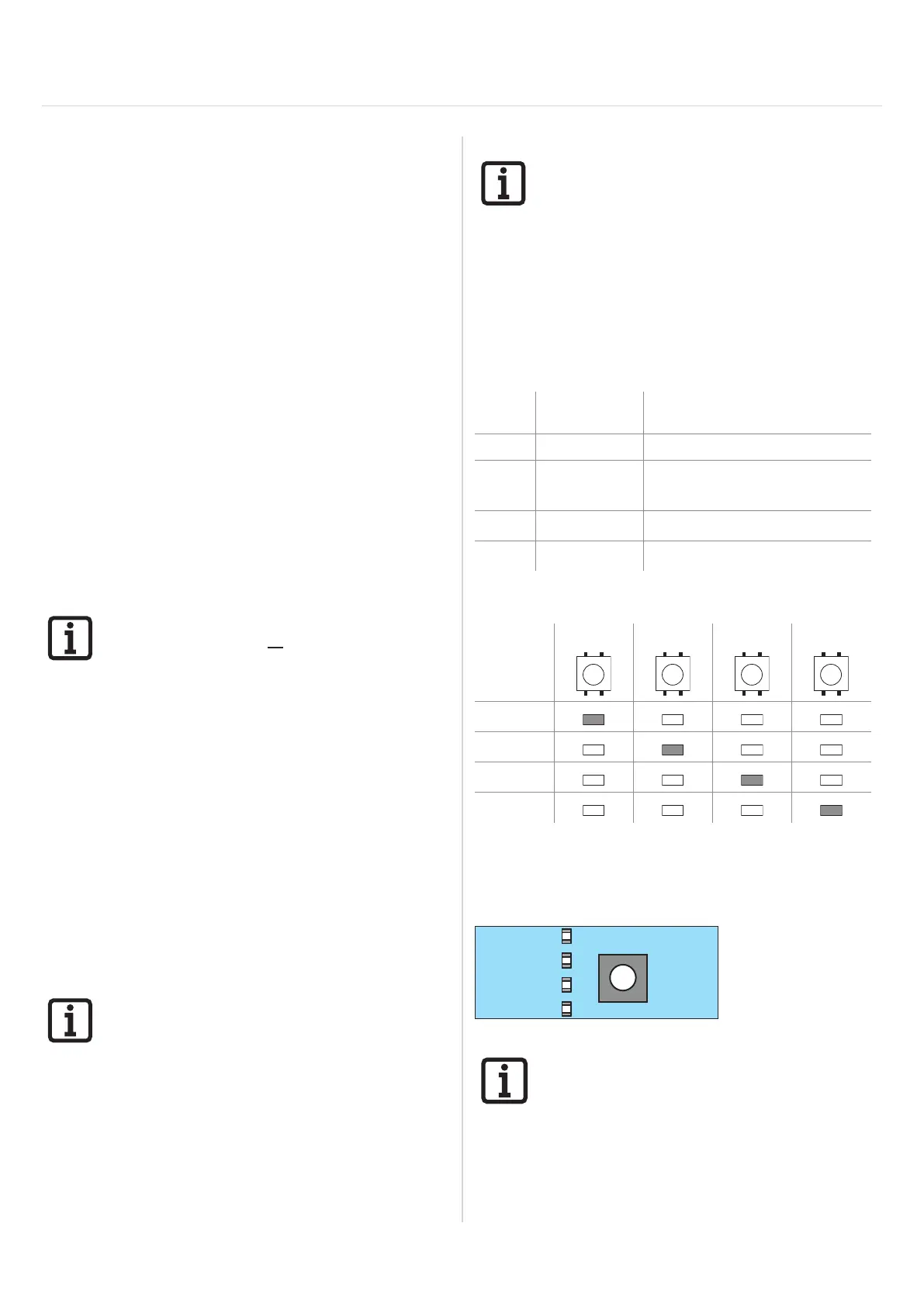
8.8 Selection of the radio channels
1 x 2 x 3 x 4 x
LED
CH 1
CH 2
CH 3
CH 4
• Press the Radio button repeatedly to select the
desired radio channel.
8.9 Programming the transmitter
RADIO
CH2
CH3
Fig. 1
INFORMATION
If no transmission command is received
within 30 seconds after pressing the Radio
button, the radio receiver switches to
normal operation.