22
DANGER
Danger due to electric current!
Contact with live parts may result in electric
currentowingthroughthebody.Electric
shock, burns, or death may result.
► Before commissioning, it is essential to
ensurethatthespecicationsonthetype
plates of the operator and the control unit
match.
► Read and observe the safety information
and warnings on page 8.
NOTE
Document initial operation!
8.1 DIP switch initial position
ON
1
2
3
4
FUNCTION
y Before starting initial operation, check that all DIP
switches are set to “OFF” (factory setting).
8. Initial operation
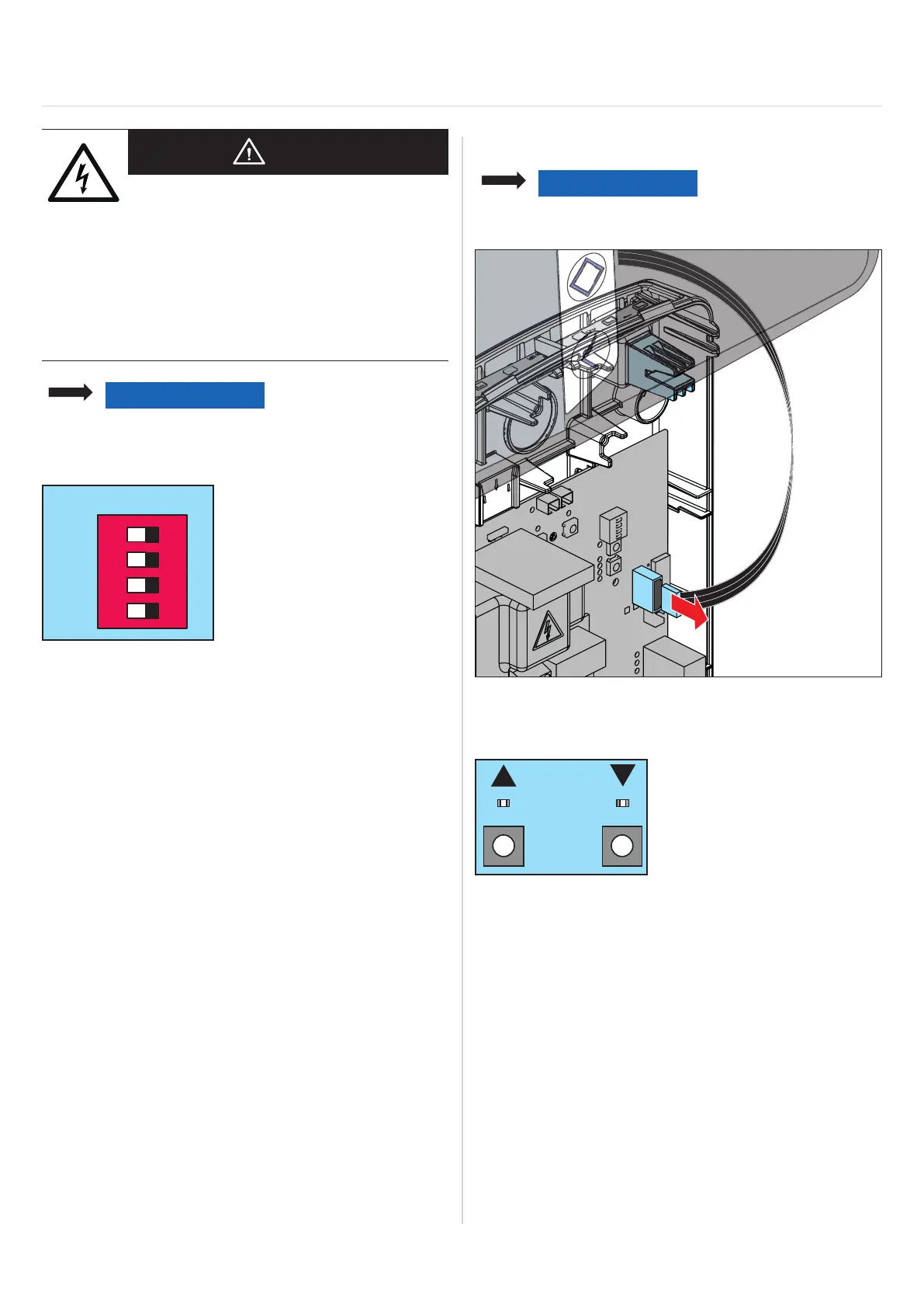
8.2 Checking the direction of running
NOTE
Only dead man mode is possible with the door
OPEN and door CLOSE buttons!
1. Move door to centre position.
2. Pull the ribbon cable of the integrated 3-function pad
off the control unit circuit board.
3. Press the door OPEN or door CLOSE button on the
circuit board.
⇒ The door moves in the desired direction:
⇒ Motor is correctly connected
⇒ The door moves in the opposite direction:
1. Turn off the control unit voltage supply.
2. Switch the connecting lines of the motor.
See “Connection overview and DIP switches” on
page 47.
3. If necessary, correct the end position setting
in accordance with the installation instructions
for the motor.