SN8P2501D
8-Bit Micro-Controller
SONiX TECHNOLOGY CO., LTD Page 47 Version 1.5
SYSTEM OPERATION MODE
5.1 OVERVIEW
The chip builds in four operating mode for difference clock rate and power saving reason. These modes control
oscillators, op-code operation and analog peripheral devices’ operation.
Normal mode: System high-speed operating mode.
Slow mode: System low-speed operating mode.
Power down mode: System power saving mode (Sleep mode).
Green mode: System ideal mode.
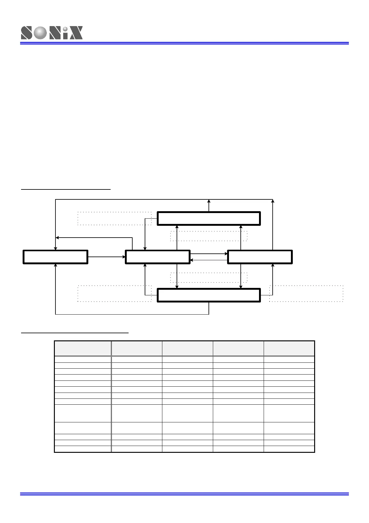
Operating Mode Control Block
Power Down Mode
Slow Mode
CLKMD = 1
CLKMD = 0
CPUM1, CPUM0 = 01.
Wake-up condition:
P0, P1 input status is level changing.
T0 timer counter is overflow.
CPUM1, CPUM0 = 10.
Normal Mode
Green Mode
Wake-up condition:
P0, P1 input status is level changing.
T0 timer counter is overflow.
Wake-up condition:
P0, P1 input status is level changing.
Reset Control Block
One of reset trigger sources actives.
One of reset trigger sources actives.
One of reset trigger sources actives.
Operating Mode Clock Control Table
By TC0ENB
Only PWM/Buzzer
active.
EHOSC: External high-speed oscillator (XIN/XOUT).
IHRC: Internal high-speed oscillator RC type.
ILRC: Internal low-speed oscillator RC type.