SN8P2501D
8-Bit Micro-Controller
SONiX TECHNOLOGY CO., LTD Page 6 Version 1.5
PRODUCT OVERVIEW
1.1 FEATURES
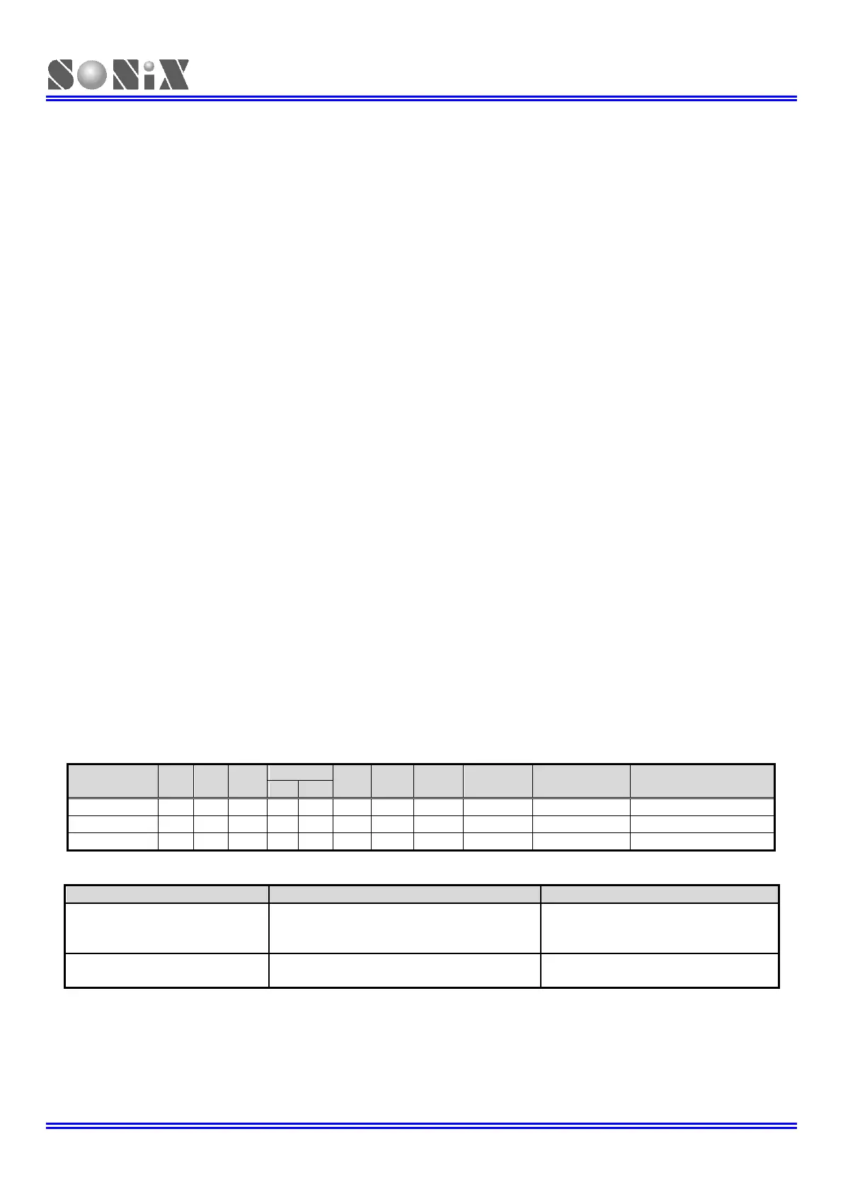
Features Selection Table
Migration SN8P2501B to SN8P2501D/SN8P2511
In RTC mode, clear T0IRQ must be after
1/2 RTC clock source (32768Hz), or the
RTC interval time is error.
IHRC_16M and IHRC_RTC modes don't
support Fosc/1 and Fosc/2.
SN8P2501D is compatible to SN8P2501B/SN8P2511.
SN8P2501B/SN8P2511 code can transfer to SN8P2501D directly. Program the original SN8 of
SN8P2501B/SN8P2511 into SN8P2501D directly with writer selection SN8P2501D chip name to program and
doesn’t need re-compile again in IDE.
Fcpu = Fosc/1, Fosc/2, Fosc/4, Fosc/8, Fosc/16.
One 8-bit basic timer with RTC (0.5Sec).
One 8-bit timer with external event counter,
2 internal interrupts: T0, TC0
On chip watchdog timer and clock source is
1 external interrupt: INT0
Internal low clock RC type (16KHz(3V), 32KHz(5V))
Bi-directional: P0, P1, P2, P5.
External high clock: RC type up to 10 MHz
Wakeup: P0, P1 level change.
External high clock: Crystal type up to 16 MHz
Pull-up resisters: P0, P1, P2, P5.
Internal high clock: 16MHz RC type
Internal low clock: RC type 16KHz(3V), 32KHz(5V)
Programmable open-drain: P1.0
External interrupt: P0.0 (PEDGE edge trigger)
Normal mode: Both high and low clock active
Slow mode: Low clock only.
Reset system and power monitor.
Sleep mode: Both high and low clock stop
Green mode: Periodical wakeup by T0 timer
Instruction’s length is one word.
Package (Chip form support)
Most of instructions are one cycle only.
All ROM area JMP/CALL instruction.
All ROM area lookup table function (MOVC).