11
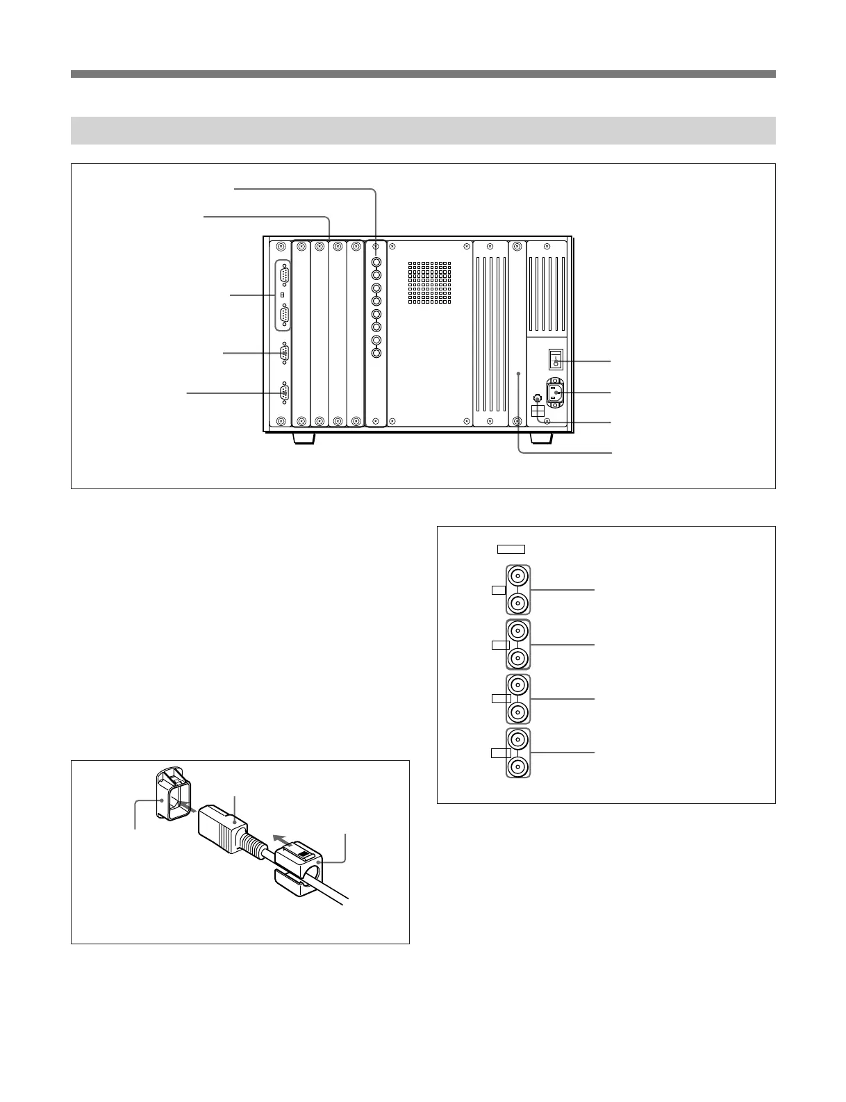
Rear Panel
1 MAIN POWER switch
When turned on, the monitor enters standby mode. By
a setting in the SYSTEM CONFIGURATION menu,
the monitor can also be set to enter operation mode
when the MAIN POWER switch is turned on.
For information about the SYSTEM CONFIGURATION
menu, see “Setting the Channel Selection Method and
Power-Up Conditions —SYSTEM CONFIGURATION
Menu” on page 43.
2 AC IN connector (3-pin)
Connects the monitor to an AC power source, via the
supplied AC power cord.
3 Fuse
Use a 4 A fuse for 100 to 120 V AC or a T 3.15 AH
fuse for 220 to 240 V AC.
4 Deflection option slot
Slot for future expansion.
5 Analog input connectors
RGB signals, component signals (Y, R–Y, and B–Y),
or composite sync signals can be fed in the IN
connectors. The type of signal applied to each
connector is set with the INPUT CONFIGURATION
menu. The OUT connectors are used for loop-through
output of the input signal. When not using loop-
through, connect a 75-ohm terminator (not supplied) to
the OUT connectors.
For information about the INPUT CONFIGURATION
menu, See “Setting the Input Configuration—INPUT
CONFIGURATION Menu” on page 32.
Y/G connectors (BNC)
B–Y/B connectors (BNC)
R–Y/R connectors (BNC)
SYNC connectors (BNC)
Cord stopper (supplied)
Plug holder
Attach the cord stopper to the AC power cord, and connect it
to the plug holder so that the cord does not come loose.
5 Analog input connectors
6 Input option slots
7 REMOTE 1 connectors
and TERMINATE
switch
9 ISR connector
8 REMOTE 2 connector
1 MAIN POWER switch
2 AC IN connector
4 Deflection option slot
3 Fuse
AC power cord (supplied)
IN
Y/G
OUT
IN
OUT
IN
OUT
IN
OUT
B-Y/B
R-Y/R
SYNC
ANALOG